|
| |
ENGINE DIVISION SERVICE MANUAL
TM 5-4210-230-14&P-1
ENGINE
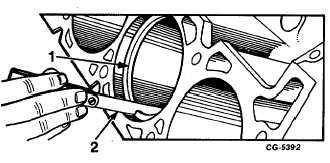
is square with the cylinder wall. Check the space or gap
between the ends of the ring with a feeler gauge, Figure 99.
See specifications for proper ring gap.
NOTE:
Extreme care should be taken during this
operation.
Fig. 99 Checking Ring Gap
1.
Piston ring
2.
Feeler Gauge
If the gap on the compression rings is less than the
limit, try the next size smaller ring. Each ring should be fitted
and checked in the cylinder in which it is to be used and
marked accordingly.
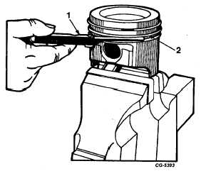
Piston rings should be checked for side clearance in
the groove of the piston on which they are to be installed.
This is done by placing the outer edge of the ring in the piston
groove, rolling the ring entirely around the piston to make sure
the ring is free in the groove. With a feeler gauge check the
side clearance
Fig. 100 Checking Ring-to-Groove Side Clearance with Feeler
Gauge
1.
Feeler Gauge
2.
Piston ring
of each ring in its respective groove, Figure 100. See
specifications for proper clearance.
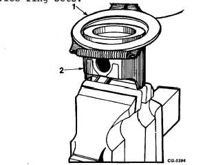
Assemble the rings on the pistons to which they were
fitted by using a piston suitable ring expander tool. This type
of tool is recommended to avoid over-expanding and also to
expand the ring to a true circle to avoid distortion, Figure 101.
General practice is to stagger the ring gaps when installing
piston rings. For further information refer to the instructions
furnished with the service ring sets.
Fig. 101 Installing Piston Ring Using Suitable Piston Ring
Expander Tool
1.
Piston ring expander
2.
Piston
Cylinder Heads, Valves, Valve Guides, Springs, Etc.
The cylinder heads, as removed from the engine,
contain the valve mechanism. The rocker arms were removed
prior to removing the heads. Position the cylinder head on the
intake manifold surface on a clean work bench or install the
cylinder head in holding fixture SE-1939 to protect the
machined
surfaces
during
cleaning
and
disassembly
operations.
With the valves installed to protect the seats, clean
the carbon deposits from the combustion chambers and valve
heads with a wire brush and scraper. Wash the heads in
cleaning solvent to remove dirt and grease from all surfaces
and dry thoroughly. Check all water passages to make sure
they are clear and open.
Examine the cylinder heads for water leaks or cracks
in the combustion chambers, exhaust ports and around the
valve seats. Inspect the machined or gasket
CGES-210 Page 37
PRINTED IN UNITED STATES OF AMERICA
|