|
| |
ENGINE DIVISION SERVICE MANUAL
TM 5-4210-230-14&P-1
ENGINE
Remove the tappet oil gallery plugs by drilling a small hole in
the plug and prying with a screwdriver or suitable tool. Clean
the tappet oil galleries with SE-2334-1 Brush (5/16" diameter).
Replace the tappet gallery plugs flush to .060" below
crankcase surface using tool shown in Figure 70. The tool
may be made locally from cold rolled steel to the dimensions
shown in Figure 70.
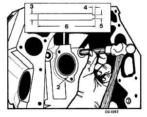
Fig. 70 Tappet Oil Gallery Plug Installation
1. Installer tool
4. .200
2. Oil hole
5. .410
3. .490
6. .450
NOTE: Coat the edges of the plugs with a
suitable nonhardening sealing compound prior to
installation.
If it becomes necessary to remove an expansion type
plug due to water leaks, drill a 1/2" hole in the center of the
plug and remove by prying with a screwdriver or suitable tool.
When installing the expansion plug, the concave side of the
plug must be installed on the interior of the cylinder block.
Coat the edges of #he plug with a suitable nonhardening
sealing compound and install using a 1" diameter brass drift
and hammer.
Inspection of the cylinder block should be done
carefully to detect any scoring of the cylinder bores, cracks or
water leaks. Small cracks may be found by coating the
suspected areas with a mixture of light motor oil and
kerosene. After wiping the area dry, immediately apply a coat
of quick drying liquid such as zinc oxide powder mixed with
wood alcohol. Wherever cracks are present, a brown
discoloration will appear in the white coating.
Check the top surface of the cylinder block for trueness
with a straightedge. Test by attempting to insert a .006" feeler
gauge ribbon between the straightedge and cylinder block
. If
this is possible, replace the cylinder block.
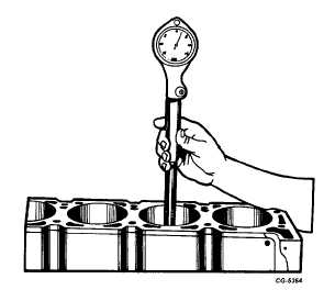
Each cylinder bore should be checked with an inside
reading micrometer SE686 or dial bore gauge SE-2331 to
determine taper, out-of-round or worn condition, Figure 71.
Measure the diameter of the cylinder bore at the top of the
piston ring travel at right angle "A", Figure 72, to the centerline
of the crankshaft. Record the readings. Next, measure each
bore so the gauge reading coincides with the centerline "B",
Figure 72, of crankshaft. The difference between "A" reading
and "B" reading is the out-of-round condition at the top of the
cylinder bore. Repeat the same procedure at the bottom of
the ring travel to check for out-of-round. The difference
between the diameters measured at the top "A" and the
bottom "B", Figure 73, of the bore (at right angles to centerline
of the crankshaft) is the taper of the bore.
Fig. 71 Checking Cylinder Bore Using Dial bore Gauge
SE-2331
CGES-210 Page 26
PRINTED IN UNITED STATES OF AMERICA
|