|
| |
ENGINE DIVISION SERVICE MANUAL
TM 5-4210-230-14&P-1
ENGINE
68.
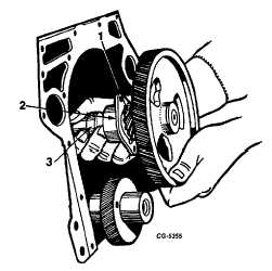
Remove the camshaft assembly, Figure 62.
IMPORTANT:
Use
extreme
caution
when
handling the camshaft assembly to prevent
chipping the distributor gear teeth.
Fig. 62 Camshaft Removal
1. Distributor gear
2. Camshaft thrust flange
3. Camshaft
NOTE: Fuel pump cam located forward of distributor
gear.
NOTE: The camshaft gear, distributor gear and fuel
pump cam can be removed without complete engine
disassembly. This can be accomplished using the
following procedure:
a.
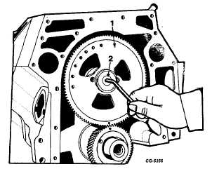
Remove camshaft allen screw, Fig. 63.
Fig. 63
1. Gear
2. Allen screw
b.
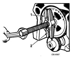
Remove camshaft gear using SE-1368 Puller, Figure
64.
Fig. 64
1. Camshaft gear
2. Puller
c.
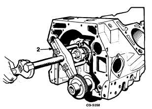
Remove fuel pump cam using SE1368 Puller and SE-
1368-3 Fingers, Figure 65.
Fig. 65
1. Fuel pump cam
2. Puller
d.
Remove distributor gear using SE-1368 Puller and SE-
1368-5 Fingers, Figure 66.
IMPORTANT: Use extreme caution so as not to chip the
distributor gear teeth.
CGES-210 Page 24
PRINTED IN UNITED STATES OF AMERICA
|