|
| |
ENGINE DIVISION SERVICE MANUAL
TM 5-4210-230-14&P-1
ENGINE
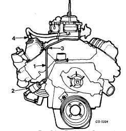
29.
Remove coil and bracket from intake manifold, Figure
30. Also, remove flame arrestor and hose from left
cylinder head cover.
Fig. 30 Coil Removal
1. Mounting bolts
2. Bracket
3. Coil
4. Flame arrestor
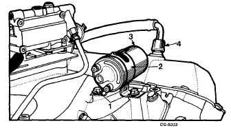
30.
Remove fuel line with bracket, reinforcement washer
and fuel filter, Figure 31. Remove PCV valve and hose.
NOTE: Cap or plug all openings or fittings.
Fig. 31 Fuel Line Removal
1. Fuel line
3. Bracket
2. Filter
4. PCV valve
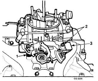
31.
Remove carburetor nuts and washers, Figure 32.
Remove carburetor, two gaskets and spacer plate.
Fig. 32 Removing Carburetor
1. Spacer
2. Nuts
3. Gasket
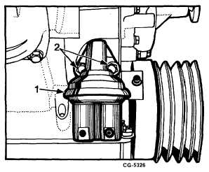
32.
Remove bolts and hardened washers securing fuel
pump to the crankcase, Figure 33. Remove fuel pump
and gasket.
Fig. 33 Fuel Pump Removal
1. Fuel pump
2. Bolts
CGES-210 Page 16
PRINTED IN UNITED STATES OF AMERICA
|