|
| |
ENGINE DIVISION SERVICE MANUAL
TM 5-4210-230-14&P-1
ENGINE
10.
Remove air cleaner.
11.
Disconnect heater hoses.
12.
Disconnect wires from alternator, coil, distributor, heat
sender unit and oil sender unit.
13.
Remove engine ground strap.
14.
Remove choke and throttle wire.
15.
Disconnect tachometer cable, if so equipped.
16.
Remove accelerator linkage at carburetor.
17.
Remove fuel line at fuel pump.
18.
Disconnect exhaust pipe at manifold.
19.
Disconnect wires at starting motor.
20.
Disconnect canister vent and purge lines at carburetor,
if so equipped.
21.
Disconnect the freon compressor wire at connector.
22.
Remove the freon compressor lines at compressor.
23.
On chassis equipped with air brakes, disconnect the
main air supply line and the flexible air line at the
compressor.
24.
On chassis equipped with hydraulic brakes having a
hydrovac, disconnect the vacuum air cleaner hose at
rear of intake manifold.
25.
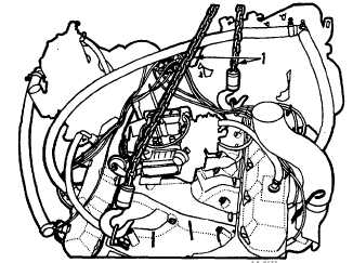
Install lifting sling, Figure 9.
26.
Connect hoist to lifting sling.
27.
Place a support under the transmission.
28.
Remove the 12 bolts securing the bell housing to
flywheel housing.
29.
Remove the engine front mounting bolts and insulators.
30.
Remove the engine rear mounting bolts and insulators.
31.
The engine must be pulled forward to clear the
transmission main drive gear and clutch driven disc;
then, raise and lift out of chassis.
NOTE: Extreme care must be exercised during removal
of the power plant to avoid damage to the clutch driven
disc and wiring harness .
Fig. 9 Engine Lifting Sling
1. Lifting sling
ENGINE INSTALLATION
Prior to installation check to be sure that all lines,
cables and parts are installed on the engine assembly that
were connected to and removed with the engine. If
maintenance was performed, be sure all adjustments affected
are made correctly. If any components of the engine were
removed and installed, check all connections and related
parts to insure the installations were accomplished correctly.
In general, the installation of the engine is performed in
the reverse order of the removal. When positioning the
engine in the chassis, special care must be exercised during
installation to avoid pinching of the wiring harness between
the engine and frame assembly.
Lower the engine to align the transmission main drive
gear spline with the clutch driven disc. The weight of the
engine assembly must be supported until the twelve bolts
securing the bell housing are installed. Connect the wiring
harness, lines and linkages that were disconnected during
removal.
Install the radiator assembly and shroud and connect
the upper and lower radiator hoses on the conventional
chassis.
On conventional chassis, install the front end sheet
metal and stay rods.
Install the hood assembly
CGES-210 Page 9
PRINTED IN UNITED STATES OF AMERICA
|