|
| |
TRUCK SERVICE MANUAL
TM 5-4210-230-14&P-1
ELECTRICAL
Grounded Side: High resistance in ground circuit of
starting motor system will result in hard starting and may
affect the charging circuit as well.
Connect voltmeter leads to ground on starting motor
and to ground post of battery. The allowable voltage drop of
.2 volt is permissible. If more than .2 volt is obtained, a poor
ground is present, such as a loose starting motor mounting
bolt, bad battery ground connector or ground connection to
engine or frame depending upon the battery installation. The
excessive voltage drop is located in much the same manner
as in the preceding test working toward the battery.
Control Circuit: High resistance in the control circuit
will reduce the current flow through the solenoid windings,
which can cause improper function of solenoid or not at all.
Improper functioning of the solenoid could result in burning of
contacts in the solenoid causing high resistance in the starting
motor circuit.
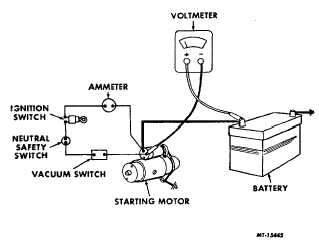
To complete control circuit test, check the vehicle
circuit diagram to assist in locating the wires and particular
switches involved in the chassis. Observe polarity of
voltmeter and connect leads to battery post and solenoid
switch terminal as shown in Fig. 5. Crank engine using the
vehicle ignition switch or push button, if equipped, observing
the voltmeter reading. If the voltmeter shows less than .5 volt,
the circuit is in good condition. If more than .5 volt, this is an
indication of excessive resistance. However, with experience,
slightly higher voltage loss will be found and will be normal.
Fig. 5 Control Circuit Test
Isolate the point of high resistance by placing the
voltmeter leads across each component in the circuit in turn.
A reading of more than. volt across any one wire or switch is
usually an indication of the trouble.
Test No. 4 -- No Load Test
After completing the cranking voltage test, battery
capacity test and voltage drop tests, and the starting motor
still fails to function, remove the motor and make the no load
test as follows.
Note that the preceding tests were made in a
particular order to make certain the starting motor circuit is in
good condition before needless starting motor removal.
Before performing "No Load Test, T" look the motor
over. The pinion should be checked to be sure it is free by
turning it on the screw shaft. The armature should be
checked so that it is free to rotate by prying the pinion with a
screw driver. Tight bearing, bent armature shaft or loose pole
shoe screw could cause the armature not to turn freely. The
motor should be disassembled if the armature does not turn
freely. However, if the armature will rotate freely, the next
step is to give the motor a no load test before disassembly.
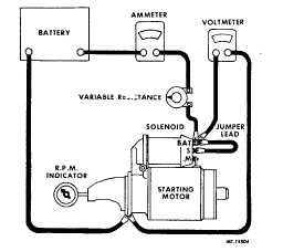
Connect the starting motor in series with a fully
charged battery of the specified voltage, an ammeter capable
of reading several hundred amperes, and a variable
resistance. Also connect a voltmeter as illustrated in Fig. 6
from the motor terminal to the motor frame. An RPM
indicator is necessary to measure armature speed. Obtain
the specified voltage by varying the resistance unit; then read
the current draw and the armature speed and compare these
readings with the values listed in the specifications.
Fig. 6 No Load Test Hookup
CTS-2258-K Page 6
PRINTED IN UNITED STATES OF AMERICA
|