|
| |
TRUCK SERVICE MANUAL
TM 5-4210-230-14&P-1
ELECTRICAL
LIGHT ASSEMBLY REPLACEMENT
1.
If necessary, clean dirt from threads of light
assembly mounting studs.
2.
Remove nuts and washers (3 each) securing light
assembly to mounting bracket.
3.
Remove mounting screws (4) securing terminal cover
to light assembly.
4.
Disconnect wiring harness connector from light
assembly.
5.
Inspect
and
clean
wiring
harness
connector
terminals. If terminals are badly corroded or
damaged, replace connector.
6.
To retard corrosion, coat terminals of new lamp
assembly and wiring harness with grease.
7.
Connect wiring harness terminal connector to light
assembly.
8.
Install terminal cover on light assembly and secure
with mounting screws.
9.
Position light assembly on mounting bracket and
secure with lock washers and nuts.
10.
Check light operation.
INSTRUMENT PANEL CONTROL LIGHT
(Located above headlight switch)
If bulb fails, it will be necessary to replace the light assembly
as follows:
1.
Remove nine (9) screws and remove instrument
panel top cover.
2.
If necessary pull light wiring up through hole in top of
instrument panel to expose wiring connector.
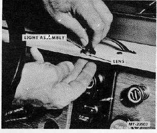
3.
Disconnect light assembly wiring connector from
wiring harness connector (Figure 17).
4.
Disengage slot of light assembly from lens to remove
light assembly (Figure 17).
Do not lose lens which can fall out of instrument
panel when light is removed.
5.
Discard old light assembly.
6.
Hold lens into hole in instrument panel and snap new
light assembly over lens to retain lens and light
assembly.
Fig. 17 Instrument Panel Control Light
7.
Connect light assembly wiring connector to wiring
harness connector.
8.
Check light operation.
9.
Install instrument panel top cover and retaining
screws.
ASHTRAY LIGHT
If bulb fails, it will be necessary to replace the light assembly
as follows:
1.
Remove ashtray from ashtray housing.
2.
Remove mounting screws* from cluster panel
holding ashtray (plus radio and auxiliary gauges,
where equipped).
* without radio; 8 with radio. On 2200 series
vehicles, 8 without radio, 10 with radio.
3.
Turn panel outward to gain access to ashtray light
(Figure 18).
4.
Disconnect light assembly wiring connector from
wiring harness connector.
5.
Disengage slot of light assembly from lens to remove
light assembly.
Do not lose lens which can fall out of ashtray housing
when light is removed.
For light assembly and lens relationship, see Figure
17.
CTS-2781S Page 10
PRINTED IN UNITED STATES OF AMERICA
|