|
| |
TRUCK SERVICE MANUAL
TM 5-4210-230-14&P-1
ELECTRICAL
5.
Connect wiring cable to new light assembly.
6.
Position light assembly on cab panel and secure with
mounting screws.
7.
Check light operation.
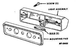
FLOOD (CARGO) LIGHT
BULB REPLACEMENT
(Refer to Figure 15)
1.
Remove light mounting screws.
2.
Pull light assembly away from mounting pad to
expose wiring cable connector.
3.
Disconnect
wiring
cable
from
light
assembly.
Remove light assembly.
4.
Disengage bulb from terminals.
5.
Position new bulb in terminals.
6.
Connect wiring cable to light assembly.
7.
Position light assembly on mounting pad and secure
with mounting screws.
8.
Check light operation.
Fig. 15 Flood (Cargo) Light
LIGHT ASSEMBLY REPLACEMENT
1.
Remove light mounting screws.
2.
Pull light assembly away from mounting pad to
expose wiring cable connector.
3.
Disconnect
wiring
cable
from
light
assembly.
Remove light assembly.
4.
Inspect light mounting pad and replace if damaged or
deteriorated.
5.
Connect wiring cable to new light assembly.
6.
Position mounting pad and light assembly on cab
and secure with mounting screws.
7.
Check light operation.
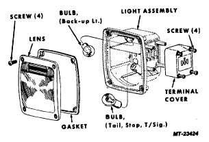
TAIL, STOP, REAR TURN SIGNAL,
BACK-UP LIGHTS
BULB REPLACEMENT
(Refer to Figure 16)
1.
Remove lens mounting screws (4).
2.
Pry lens from light assembly.
3.
Press bulb in lightly and turn counter-clockwise to
disengage retaining pins.
4.
Pull bulb from socket.
5.
Inspect lens and gasket and replace if damaged.
6.
Install new bulb as follows:
a.
Align retaining pins with slots in socket.
Stop, tail, turn signal bulb has staggered
retaining pins to assure correct positioning in
socket.
b.
Push bulb into socket and turn clockwise to
secure retaining pins.
7.
Position gasket and lens in light assembly and
secure with screws.
8.
Check light operation.
Fig. 16 Tail, Stop, Rear Turn Signal, Back-up Light
CTS-2781 Page 9
PRINTED IN UNITED S TATES OF AMERICA
|