|
| |
TRUCK SERVICE MANUAL
TM 5-4210-230-14&P-1
ELECTRICAL
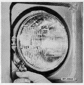
Fig. 6 Disconnecting Headlight Retainer Spring
4.
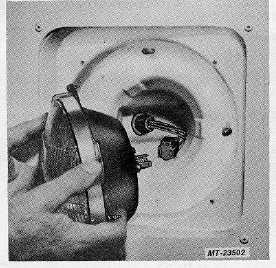
Disconnect three-way wiring connector from rear of
sealed beam unit and remove headlight assembly
(Figure 7).
Fig. 7 Removing Headlight Assembly
5.
To remove sealed beam assembly from mounting
ring (if necessary):
a.
Remove three (3) retaining screws and
remove sealed beam retaining ring (Figure 4).
b.
Remove sealed beam unit from mounting ring.
6.
If replacement of headlight retaining spring is
required:
a.
Remove spring retaining screw and remove
spring from hood (fender).
b.
Position new spring on hood (fender) and
secure with retaining screw.
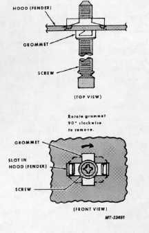
7.
If required, replace headlight adjusting screw(s) as
follows: (Refer to Fig. 8).
a.
While pushing screw inward (toward rear of
vehicle) rotate grommet (nut) ninety degrees
(900) clockwise until front tangs of grommet
align with slot in hood (fender).
b.
Extract screw (with grommet) working from
wheel side of hood (fender).
c.
Position new screw and grommet assembly in
hood (fender). Align front retaining tangs on
grommet with slot in hood and push screw
assembly forward as far as possible.
d.
Rotate
grommet
ninety
degrees
(90
)
counterclockwise until retainer tabs on rear
tangs engage with slot in hood (fender) and
front tangs are perpendicular to slot.
Fig. 8 Adjusting Screw Mounting Details
CTS-2781S Page 5
PRINTED IN UNITED STATES OF AMERICA
|