|
| |
TRUCK SERVICE MANUAL
TM 5-4210-230-14&P-1
ELECTRICAL
INTRODUCTION
Outlined below are service procedures covering lights
used on typical S-Series vehicles. Some vehicles may be
equipped with additional accessory lights which are not
covered herein.
When diagnosing light failure, first check for a
"blown" fuse or tripped circuit breaker. Fuse sizes and
locations are listed in the circuit diagram section of the Truck
Service Manual Refer to the appropriate section covering the
model year of the vehicle being serviced. If a "blown" fuse or
tripped circuit breaker is found, inspect wiring circuit for cause
of overload and make necessary repairs.
If fuse or circuit breaker is satisfactory, check for
"burned out" light bulb and replace if necessary. Light bulb
types used in various lights are listed in the LIGHT BULB
CHART in this section.
If light bulb is good, check wiring and connectors for
an "open" circuit. A 12-volt test light can be used to check
circuit continuity. Refer to the appropriate wiring circuit
diagram.
HEADLIGHTS
HEADLIGHT AIMING
Various types of headlight aiming equipment are
available commercially. When using aiming equipment,
follow instructions provided by the equipment manufacturer.
Where headlight aiming equipment is not available,
headlight aiming can be checked by projecting the upper
beam of each light upon a screen or chart at a distance of
about 25 feet ahead of the headlights. The truck should be
exactly perpendicular to the chart.
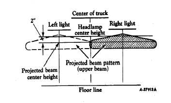
Fig. 1 Headlight Aiming Pattern
The vertical lines on the chart (Figure 1) mark the
distance between the vertical center lines of the headlights
and are equally spaced from the center line of the chart.
A horizontal line should be placed on the chart at a
level of two (2) inches below the height of the headlight
centers above the floor.
With headlights on "HIGH" beam, the "hot spot" of
each projected beam pattern should be centered over the
point of intersection of the vertical and horizontal lines on the
chart, as shown in Figure 1.
If necessary, adjust headlights vertically and/or
laterally
to
obtain
proper
aim.
(See
HEADLIGHT
ADJUSTMENT).
IMPORTANT
Headlight aim should always be checked on a
level floor with the vehicle unloaded.
In some states, the above instructions may
conflict with existing laws and regulations.
Where this is the case, legal requirements
must be met.
Modify the instructions accordingly.
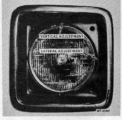
HEADLIGHT ADJUSTMENT
Adjusting screws are provided to move the headlight
assembly in relation to the hood (fender) to obtain correct
headlight aim.
Lateral or side-to-side adjustment is accomplished by turning
adjusting screw at side of headlight (Figure 2).
Vertical or up-and-down adjustment is accomplished by
turning adjusting screw at top of headlight (Figure 2).
Fig. 2 Headlight Adjusting Screws
CTS-2781S Page 3
PRINTED IN UNITED STATES OF AMERICA
|