|
| |
ENGINE DIVISION SERVICE MANUAL
TM 5-4210-230-14&P-1
5.
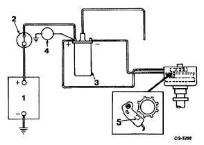
Test primary voltage.
"Bump" starter to position sensor coil between two
trigger wheel teeth (see Figure 50).
Connect voltmeter between coil positive (+) terminal
and ground. Turn ignition switch "on" and observe
voltmeter. If voltmeter reads battery voltage (12-
13V), proceed to step 6.
If voltage is noticeably lower than battery voltage, a
high resistance exists between battery (through
ignition switch) and coil which must be located and
repaired. (See Primary Voltage Drop Test).
Fig. 50 Testing Primary Voltage
1. Battery
4. Voltmeter
2. Ignition Switch
5. Sensor Coil Between
3. Ignition Coil
Two Trigger Wheel
Teeth
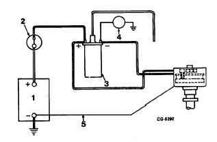
6.
Test voltage at coil negative (-) terminal.
Sensor coil should be between two trigger wheel
teeth. Connect voltmeter between coil negative (-)
terminal and ground (Figure 51).
With ignition switch "on", one of the following
voltmeter readings will be obtained: (A) 5 to 8 volts
(normal) (B) 12 to 13 volts (problem area) (C) 0 to 5
volts (problem area)
A.
If voltage is 5 to.8 volts:
Proceed to Step 7.
B.
If voltage reading is 12 to 13 volts:
Connect jumper wire between distributor housing and
battery negative (-) terminal (Figure 52). Observe
voltmeter.
Fig. 51 Testing Voltage at Coil Negative
(-) Terminal
1. Battery
3. Ignition Coil
2. Ignition Switch
4. Voltmeter
If voltage remains at 12 - 13 volts, electronic control
unit in distributor is faulty and must be replaced.
If voltage changes to 5 - 8 volts with jumper wire
connected, a problem exists in the ground circuit
between the distributor and the battery. Check
battery negative (-) cable (at battery and engine) and
cab-to-engine ground strap and/or other ground
straps. Repair as needed.
Fig. 52. Testing With Jumper Wire Between Dist. Housing
and Batt. (-) Terminal.
1. Battery
4. Voltmeter
2. Ignition Switch
5. Jumper Wire
3. Ignition Coil
CGES-145-U Page 25
PRINTED IN UNITED STATES OF AMERICA
|