|
| |
ENGINE DIVISION SERVICE MANUAL
TM 5-4210-230-14&P-1
Fig. 1 Schematic View of Ignition System
1.
Battery
5.
Trigger Wheel
2.
Ignition Switch
6.
Electronic Control
3.
Ignition Coil
7.
Sensor
4.
Spark Plug
8.
Air Gap
DESCRIPTION
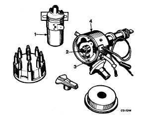
The electronic (breakerless) ignition system (Figure
1)consists of two major component units-a distributor and an
ignition coil. These units are shown in Figure 2.
Fig. 2 Major Components of Ignition System
1.
Ignition Coil
3.
Electronic Control
2.
Trigger Wheel
Unit
4.
Distributor
The distributor is conventional except that a trigger
wheel and an electronic control unit (circuit board and sensor)
replace the usual distributor cam, contact points and
condenser. A standard type ignition coil is used.
The electronic control unit (Figure 3) is associated with
the primary (low voltage) section of the ignition system. The
control unit electronically "makes" and "breaks" the ignition
primary circuit in response to rotation of the trigger wheel.
Fig. 3 Electronic Control Unit (Circuit Board, Sensor and Plate
Assembly)
1.
Sensor
3.
Mounting Plate
2.
Sensor Plate
4.
Electronic Circuit
Board
The control unit circuit board is a completely solid state
unit designed for trouble free service. Its electronic
components are permanently sealed in a waterproof and
vibration resistant compound.
The sensor is a small coil, wound of fine wire, which is
very simply a metal detector. The metal that the sensor
detects is the teeth of the trigger wheel.
The electronic circuit board and sensor are mounted on
the distributor plate assembly. The sensor leads are soldered
directly to the circuit board. The electronic control unit (circuit
board, sensor and plates) is provided for service 'as a
complete assembly.
CGES-145-U Page 3
PRINTED IN UNITED STATES OF AMERICA
|