|
| |
TRUCK SERVICE MANUAL
TM 5-4210-230-14&P-1
ELECTRICAL
significantly from these figures. Before condemning
a rotor for an open coil, check the solder joints at the
slip ring leads, as a poor connection at either of
these leads will test the same as an open coil. If the
proper resistance is not obtained after resoldering
these connections, discard the rotor.
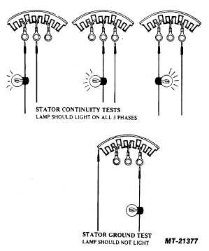
STATOR TEST
Due to the extremely low resistance of the stator
windings it is difficult to measure their resistance with a
conventional ohmmeter. The stator should therefore be tested
for grounds and continuity between phases with a test light. A
12 volt test light is preferred.
Do not attempt to check stators in this manner while
they are still connected to the heat sinks. Remove the stator
from the alternator before testing (see Fig. 22 for stator test).
Discard any stators which appear overheated and have
charred insulation, regardless of how they test.
Several stators are available which can be used as
service replacements on these alternators. The part numbers
of these stators will be listed in the appropriate parts list.
SLIP RING REPLACEMENT
The slip ring assembly used in these alternators is of
extremely sturdy construction and will seldom require
replacement. If it should become damaged in some way,
such as dropping the rotor, it may be replaced in the following
manner.
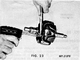
1. Unsolder the slip ring leads and lift them clear of the
eyelets which serve to retain them to the rotor coil leads.
Do not lose or damage the eyelets (see Fig. 23).
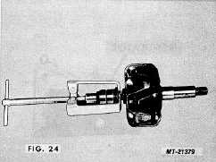
2. With a suitable puller, the slip ring assembly may now be
pulled from the shaft (see Fig. 24).
3. Clean the rotor shaft and apply a small amount of Loctite
to the shaft on the section normally occupied by the slip
ring assembly.
4. Position the new slip ring assembly on the shaft so that the
two leads are aligned with the two rotor coil eyelets on the
rotor, and carefully press the slip ring assembly onto the
shaft.
FIG. 22
CTS-2743T Page 10
|