|
| |
TRUCK SERVICE MANUAL
TM 5-4210-230-14&P-1
3.
When new thick lining is installed, cups are pushed
closer
together
and
must
function
over
the
roughened surface.
4.
Since cups no longer seat against smooth cylinder
walls, they allow fluid to leak out.
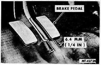
BRAKE PEDAL ADJUSTMENT
When the brake control system is in the released
position, the foot brake pedal should have 6.4 mm (1/4") free
travel (Fig. 1) before the pressure stroke starts. This free
travel is required to prevent blocking of the compensating port
in the master cylinder. Brakes will drag if the compensating
port becomes blocked due to pressure building up in the
system. Shorten the pedal stop rod to allow the piston to
uncover the compensating port allowing fluid to escape into
the reservoir.
Fig. 1. Brake Pedal Free Travel
BLEEDING BRAKE SYSTEM
The hydraulic brake system must be free of air to
function properly. If air becomes mixed with the brake fluid,
loss of pedal reserve will result since the air in the hydraulic
system compresses. A bleeder valve (screw) is provided at
each wheel cylinder for removal of any air in the hydraulic
brake system.
Bleeding the brake system consists of forcing brake
fluid and any air in the brake fluid out of the hydraulic system
at one or more bleed points. There are two methods of
bleeding the hydraulic brake system; manual bleeding and
pressure bleeding. For either method of bleeding, a supply of
clean hydraulic brake fluid is necessary. Do not reuse brake
fluid that has been drained from the hydraulic brake system,
as the fluid may be contaminated or contain dirt.
The order in which wheel cylinders are bled normally
does not affect the quality of the bleeding operation. The
following sequence is recommended, however, to reduce the
possibility of missing a wheel cylinder: right rear, left rear,
right front, left front.
PRESSURE BLEEDING
A pressure bleeder with adapter plate for connection
to the master cylinder reservoir is necessary to pressure bleed
the brake system. The adapter plate is designed to permit a
transfer of fluid to maintain fluid level during brake bleeding.
Hydraulic brake fluid level should be approximately
12.7 mm (1/2") from top of master cylinder reservoir. If, when
pressure bleeder adapter plate is removed, fluid level is too
high or too low, add or remove sufficient fluid to bring to
correct level.
Be sure there is enough brake fluid in the bleeder
tank to complete the bleeding operation and the tank is
charged with 69-207 kPa (10 30 psi) air pressure.
Remove reservoir cover and attach pressure bleeder
hose to master cylinder using proper adapter. Open the valve
in the pressure bleeder hose to pressurize the master cylinder
and hydraulic system.
Attach a bleeder tube (hose) to right rear wheel
cylinder bleeder valve (screw), Fig. 2. Submerge the free end
of the hose in a glass jar partially filled with brake fluid.
Loosen bleeder valve approximately three-quarter's turn.
When fluid coming from the submerged end of the
hose is free of air bubbles, close bleeder valve and remove
drain hose. Repeat this procedure at each wheel cylinder.
When bleeding operation is completed, close the
valve in the pressure bleeder hose. Enclose connection with
shop towel and disconnect pressure bleeder and adapter from
master cylinder.
Check hydraulic fluid level to see that reservoir is
filled to within 12.7 mm (1/2") from top edge.
Install master cylinder reservoir cover.
MANUAL BLEEDING
Fill the master cylinder fluid reservoir with clean
brake fluid. Attach a bleeder tube hose to the right rear wheel
cylinder bleeder valve (screw). Submerge the free end of the
hose in brake fluid in a partially filled glass jar, Fig. 2.
CTS-2055S Chapter III Page 4
PRINTED IN UNITED STATES OF AMERICA
|