|
| |
TRUCK SERVICE MANUAL
TM 5-4210-230-14&P-1
BODIES AND CABS
IMPORTANT
Always disconnect battery ground strap before
servicing or removing electrical components.
Control Switch
1.
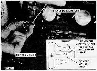
Remove control knob for electric control switch by
depressing retaining clip on back of knob with offset or
small screwdriver (Fig. 6).
Fig. 6 Removing Control Knob from Switch
2.
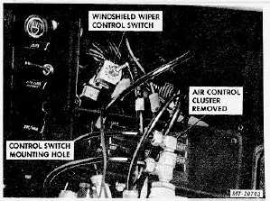
Remove mounting screws and detach panel to right of
wiper control switch and above heater controls.
Fig. 7 Removing Wiper Switch from Instrument Panel
3. Remove mounting nut from switch shaft and demount
switch assembly from instrument panel (Fig. 7).
4.
Disconnect wiring leads and remove switch.
INSTALLATION
Reinstalling of windshield wiper system components is
the reverse of removal. Be careful when installing cowl cover
panel so as to protect windshield seal from damage. When
returning wiper arms to drive shafts, control switch should be
in "off" position and blades should be positioned in "park"
position on windshield (50 mm or 2 inches up from bottom of
windshield). If blades do not park as specified, see
"ADJUSTMENT". When blades are correctly positioned,
install cap nut and tighten to 6-7 Nm (55-60 in .lbs. ).
MAINTENANCE
Service on the windshield wiper system is limited to the
replacement of components shown in Fig. 1. Disassembly of
either the electric wiper motor or the control switch is not
recommended.
ADJUSTMENT
1. Operate wiper motor and turn control switch on instrument
panel to "OFF". Wiper blades should automatically
move to "park" position on windshield (50 mm or
approx. 2 inches up from bottom of windshield).
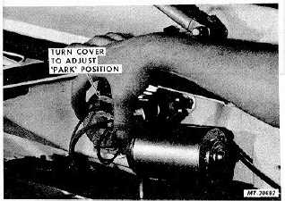
Fig. 8 Adjusting Wiper Blade Park Position
2. If adjustment is required, loosen motor cover mounting
screws and turn cover clockwise or counterclockwise
as required to set correct "park" position (Fig. 8).
Retighten cover screws. (Length of stroke is fixed and
cannot be changed.)
CTS-2732 Page 3
PRINTED IN UNITED STATES OF AMERICA
|