|
| |
TRUCK SERVICE MANUAL
TM 5-4210-230-14&P-1
BODIES AND CABS
b.
Disconnect radio power feed wire, speaker
leads and antenna lead from radio.
c.
If necessary, disconnect hourmeter, front
wheel
drive
warning
light,
engine
oil
temperature
gauge
and
transmission
oil
temperature gauge wiring.
d.
Disconnect ash tray light from ash tray frame.
e.
Remove radio/ash tray panel.
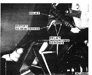
4.
Using offset screwdriver or screwdriver socket,
remove relay mounting screws and remove relay(s)
from air duct (Fig. 52).
5.
Disconnect wiring harness connectors from relay(s).
Fig. 52 Removing Relay
Installation:
1.
Connect wiring harness connectors to relay(s).
2.
Position relay(s) on air duct and install mounting
screws. Use offset screwdriver or screwdriver socket
to tighten screws.
3.
Reinstall radio/ash tray panel and related parts (if
removed).
4.
Reconnect battery cables.
5.
Turn key switch "ON" and check operation of
relay(s). Turn key switch "OFF" after operation
check.
6.
Install instrument panel cover.
HOT WATER FLOW CONTROL VALVE
Removal:
1.
Raise hood and fender assembly.
2.
Drain engine cooling system.
3.
Remove cover from right side of instrument panel.
4.
Remove cover from heater/evaporator unit.
5.
Remove heater core as follows:
a.
Loosen hose clamps at heater core.
b.
Open blend air door.
c.
Remove heater core mounting screws.
d.
Disconnect hoses from heater core and pull
core outward to remove.
6.
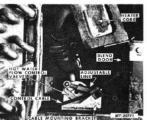
Remove
control
cable
mounting
screw
from
mounting bracket (Fig. 53). Disconnect control cable
from blend air door.
Fig. 53 Hot Water Flow Control Valve Connection Details
7.
Loosen hose clamp and disconnect inlet hose
(located beneath heater/evaporator unit housing)
from neck of flow control valve.
8.
Remove flow control valve mounting screws. (Screw
heads are located on bottom of heater/ evaporator
unit housing.)
CTS-2731 Page 36
PRINTED IN UNITED STATES OF AMERICA
|