|
| |
TRUCK SERVICE MANUAL
TM 5-4210-230-14&P-1
BODIES AND CABS
4.
Using two wrenches, remove fan drive override
switch from compressor discharge service port.
CAUTION
A small amount of refrigerant may escape from service port
valve while switch is being removed.
Installation:
1.
Lubricate threads of fan drive override switch and
position switch on compressor discharge service
port.
2.
Using two wrenches, tighten fan drive override
switch.
3.
Connect switch wires to engine wiring harness.
4.
Lower hood and fender assembly.
FAN DRIVE OR SHUTTER CONTROL SOLENOID
VALVE
Removal:
1.
Make sure key switch is "OFF".
2.
Raise hood and fender assembly.
3.
Bleed pressure. from vehicle's air system.
4.
Disconnect solenoid feed wire from solenoid valve.
5.
Disconnect air hoses from solenoid valve.
6.
Remove mounting screws and remove solenoid valve
from mounting bracket.
7.
Remove air pipe fittings from solenoid valve.
Installation:
1.
Install air pipe fittings in solenoid valve.
2.
Position solenoid valve on mounting bracket and
install mounting screws.
3.
Connect air hoses to solenoid valve.
4.
Connect feed wire to solenoid valve.
5.
Lower hood and fender assembly.
FILTER-DEHYDRATOR
IMPORTANT
Filter-dehydrator should be replaced whenever air conditioning
system is opened to service components.
System must be discharged before removing filter-dehydrator.
Removal:
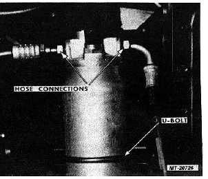
1.
Disconnect
inlet
and
outlet
hoses
from
filterdehydrator. Cap or tape hoses openings to
prevent entry of foreign material.
2.
Loosen U-bolt and remove filter-dehydrator from
mounting bracket (Fig. 50).
Fig. 50 Filter-Dehydrator Mounting
Installation:
1.
Position filter-dehydrator in mounting bracket. Make
sure inlet and outlet openings index and align with
their corresponding hoses.
2.
Tighten mounting U-bolt to 15-18 N.m (11-14 ft.lbs.).
3.
Remove plug from inlet opening of filterdehydrator.
Remove cap or tape from inlet hose. Lubricate
threads with refrigerant oil and connect inlet hose to
filter-dehydrator.
CTS-2731 Page 34
PRINTED IN UNITED STATES OF AMERICA
|