|
| |
TRUCK SERVICE MANUAL
TM 5-4210-230-14&P-1
BODIES AND CABS
2.
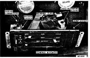
Remove control assembly mounting screws. Remove
control assembly trim plate. Pull control assembly
outward (Fig. 44). It may be necessary to remove
ash tray to allow movement of control assembly.
3.
Disconnect wiring harness connector from blower
switch.
4.
Disconnect instrument panel lamp socket from
control assembly as follows:
a.
Rotate lamp socket clockwise (as viewed from rear of
vehicle).
b.
Pull lamp socket (with bulb) from control assembly.
5.
Remove control cable to control lever retaining clips.
Remove
control
cable
mounting
screws
and
disconnect control cables from control levers.
6.
Remove control assembly.
Fig. 44 Removing Control Assembly
Installation:
1.
Connect control cables to control assembly levers as
follows:
a.
Cable with red mounting tab to upper (A/C) lever.
b.
Cable with white mounting tab to center (HTR) lever.
c.
Cable with black mounting tab to lower (AIR
OUTLET) lever.
Install control cable mounting screws and cable
retaining clips.
2.
Connect instrument panel lamp socket to control
assembly.
3.
Connect wiring harness connector to blower switch.
4.
Position control assembly in instrument panel and
install trim plate and mounting screws.
5.
Check operation and adjustment of control cables as
outlined under "Control Cable Adjustment" .
CONTROL CABLE REPLACEMENT
Removal:
1.
Disconnect battery cable from battery.
2.
Remove cover from right side of instrument panel.
3.
Remove cover from heater/evaporator unit.
4.
Remove control assembly mounting screws. Remove
control assembly trim plate. Pull control assembly
outward. (It may be necessary to remove ash tray to
allow movement of control assembly.)
5.
Remove control cable-to-control lever retaining clips.
Remove
control
cable
mounting
screws
and
disconnect cable(s) from control lever(s)(Fig. 44)
cables can be identified by the colored cable
mounting tabs:
Air Conditioning (A/C) Cable
Red Tab
Heater (HTR) Cable
White Tab
Air Control Cable
Black Tab
6.
Disconnect opposite end of cable(s) as follows:
Air Conditioning (A/C) Cable
a.
Remove cable mounting screw from thermostatic
control switch bracket (Fig. 45).
b.
Remove thermostatic control switch mounting switch
from bracket.
c.
Remove retainer clip and disconnect cable from
switch lever.
Heater (HTR) Cable
a.
Remove control cable mounting screw from cable
mounting bracket (Fig. 45).
b.
Disconnect cable from blend air door.
c.
Withdraw
end
of
cable
through
hole
in
heater/evaporator unit housing.
CTS-2731 Page 29
PRINTED IN UNITED STATES OF AMERICA
|