|
| |
TRUCK SERVICE MANUAL
TM 5-4210-230-14&P-1
BODIES AND CABS
Relative positions of heater core, evaporator core,
blower fan and motor and other components located in the
combination unit are shown in Fig. 3. These components are
described in detail later in this .section.
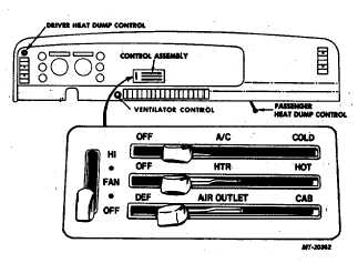
Control Panel Assembly
Major functions of the heater and air conditioning
systems are controlled from the control panel assembly (Fig.
4). The control panel has three levers (two levers on vehicles
with heater only) and a blower switch.
Fig. 4 Control Assembly
The top (A/C) lever operates the air conditioning
thermostatic control switch to regulate cab cooling (air
conditioning). The center lever (HTR) operates the hot water
flow control valve and the blend door to regulate cab heating.
The lower (AIR CONTROL) lever divides air flow between
DEFROST and CAB AIR outlets.
Separate controls (not in control panel) are provided
for operating the fresh air ventilation system and the driver
and passenger floor heat dumps.
The three speed blower switch has five terminals.
Feed current from a 20 amp fuse enters the switch through
terminal "B". Whenever switch lever is moved from the "OFF"
position, current is provided through the terminal "A/C" to the
thermostat control switch. Terminals "L", "M" and "H" refer to
low, medium and high speeds and are energized when the
switch lever is moved to their corresponding positions. On
vehicles with heater only, the "L", "M" and "H" terminals are
wired to the resistor terminals "4", "3" and "1" respectively.
On vehicles with air conditioning, the "H" terminal is wired to
terminal "4" of the high speed relay. (See wiring circuit
diagrams, Figs. 16 and 17.)
The ventilation system is controlled by rotating the
"VENT" knob located just to the left of the center instrument
panel air outlets. The driver floor heat dump is cable operated
from a push-pull control located at the upper left hand corner
of the instrument panel. The passenger floor heat dump is
operated by a hand lever located under the instrument panel.
Heater Core
The heater core (Fig. 3) is mounted in the
combination unit housing. The core is of honeycomb
construction. Engine coolant is circulated through the core
water passages and heat from the coolant is dissipated to air
circulated through the core fins.
Hot Water Flow Control Valve
The hot water flow control valve regulates the flow of
hot engine coolant through the heater core. The control valve
operates in conjunction with the blend door (Fig. 3).
This
arrangement
is
controlled
through
cable
connected to the second (HTR) lever on the control panel
assembly. In the "OFF" position, no coolant is allowed to flow
through the heater core and the blend door is in the full open
position, bypassing air around the heater core. As the lever
moves toward the maximum heat position, the flow of coolant
through the core is increased and the air bypassing the core is
reduced until at maximum lever travel (HOT) all air flows
through the core.
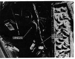
Blower
The blower fan (Fig. 5) provides air circulation
through the heater and evaporator cores and delivers the
treated air to the cab interior.
Fig. 5 Air Blower and Resistor
CTS-2731 Page 5
PRINTED IN UNITED STATES OF AMERICA
|