|
| |
TRUCK SERVICE MANUAL
TM 5-4210-230-14&P-1
3.
Retain shim pack as an aid to adjustment on
reassembly. Do not damage shims.
4.
If difficulty is encountered in lifting the cage from the
carrier, place a brass drift on the inner end of pinion and tap
pinion and cage out of differential housing.
NOTE
Do not allow pinion and cage assembly to fall
or damage may result.
When tapped holes for puller screws are provided, removal of
the pinion and cage is as follows:
1.
Hold the companion flange or yoke and remove
pinion shaft nut and washer.
2.
Remove flange with a suitable puller.
3.
Remove pinion cage stud nuts or capscrews.
4.
Remove bearing cover and oil seal assembly.
5.
Insert puller screws in the cage flange and remove
pinion and cage assembly.
NOTE
Using a drift to drive on inner end of pinion of
this type axle will damage the bearing lock
ring groove.
6.
Retain shim pack as an aid to adjustment on
reassembly.
Disassemble Pinion and Cage Assembly
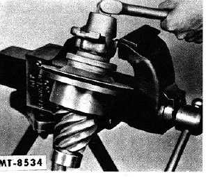
1.
If the companion flange or yoke has not previously
been removed from pinion, mount the pinion and
cage assembly in a vise. Remove the cotter pin and
take off pinion and nut as shown in Fig. 17.
Fig. 17 Pinion and Cage Disassembly
2.
Tap or drive the pinion assembly from flange and out
of cage using a soft hammer.
3.
Remove outer bearing from cage.
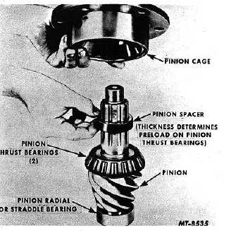
4.
Remove spacer or spacer combination from pinion
shaft, Fig. 18.
5.
If it is necessary to remove the rear thrust bearing on
the radial bearing, Fig. 18, remove these bearings
with a suitable puller
Fig. 18 Removing Pinion Bearing Spacer
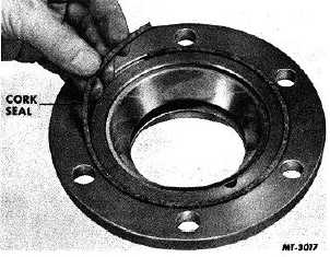
6.
Remove cork seal from pinion cage, Fig. 19. (This
seal should be replaced at every disassembly.) If the
pinion cage assembly is the type which is removed
from the carrier by means of puller screws, remove
the oil seal from bearing cover.
Fig. 19 Removing Pinion Cage Seal
CTS-2095S-CHAPTER I-Page 8
PRINTED IN UNITED STATES OF AMERICA
|