|
| |
TRUCK SERVICE MANUAL
TM 5-4210-230-14&P-1
TRANSMISSION
Parts that have been cleaned, dried, inspected and are to
be immediately reassembled should be coated with light oil to
prevent corrosion. If these parts are to be stored for any
length of 'time, they should be treated with a good rust
preventive and wrapped in special paper or other material
designed to prevent corrosion.
Repair
Replace all worn or damaged parts. Hex nuts with
rounded corners, all lockwashers, oil seals and gaskets
should be replaced at the time of overhaul.
Use only genuine International replacement parts for
satisfactory service. For example, using gaskets of foreign
material generally leads to -mechanical trouble due to
variations in thickness and the inability of certain materials to
withstand compression, oil, etc.
Remove nicks, mars and burrs from machined or ground
surfaces. Threads must be clean and free to obtain accurate
adjustment and correct torque. A fine mill file or India stone is
suitable for this purpose. Studs must be tight prior to
reassembling the parts.
When assembling component parts use a press
where possible.
Tighten all nuts to correct torque. :(See torque limits
following service instructions.) Use soft iron locking wire to
prevent possibility of wire breakage.
The burrs, caused by lockwashers, at the spot face of
stud holes of cages and covers should be removed to assure
easy reassembly of these parts.
ASSEMBLY
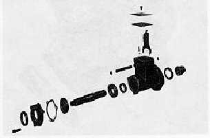
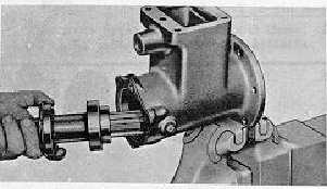
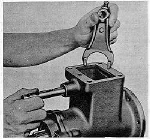
Assembly of Power-Take-Off
Fig. 21.
Fig. 22.
1.
Install ball bearings on power-take-off shaft.
2.
Position wiper against inner bearing. Install snap ring in
groove of outer bearing.
3.
Slide shaft assembly into housing and install sliding
clutch on inner end (Fig. 22).
4.
Position a new gasket and install oil seal cage assembly.
Secure with capscrews and lockwashers.
5.
Place shift fork in groove of sliding clutch. Slide shift shaft
into bore of fork (Fig. 23).
6.
Line up recess in shaft with set screw and tighten screw.
Lock wire the set screw to fork.
7.
Install expansion plug in shist shaft hole. If necessary,
replace shift shaft oil seal located in front of housing.
Fig. 23.
CTS-2048Q Page 9
PRINTED IN UNITED STATES OF AMERICA
|