|
| |
TM 5-4210-230-14&P-1
TRUCK SERVICE MANUAL
STEERING
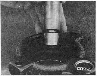
Fig. 24. Install New Needle Bearing,
ASSEMBLY
1.
Install shaft and bearing assembly (Fig. 18). Secure
with retaining ring (Fig. 17).
2.
Lubricate the reservoir, pressure-plate, and end-plate
"O" rings with power steering fluid and install into pump
housing (Figs. 4, 10 and 12).
3.
Insert two dowel pins into housing - press on pins to
seat fully (Fig. 25).
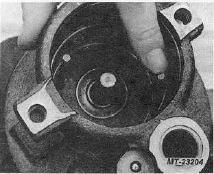
Fig. 25. Install Dowel Pins
4.
Pilot thrust plate on dowel pins and push down until
thrust plate bottoms on housing (Fig. 26).
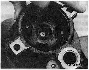
Fig. 26 Install Thrust Plate
5.
Guide pump ring onto dowel pins and seat against
thrust plate (Arrows on ring up) (Fig. 27).
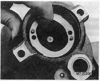
Fig. 27 Install Pump Ring
6.
Slide rotor onto drive, shaft splines, then assemble ten
vanes into rotor slots with rounded edges of vane out.
Rounded edges must ride against ring cam (Fig. 28).
7.
Squirt power steering fluid onto vanes and rotor and
ring cam (Fig. 29) (Lubrication prevents internal
damage at initial start).
CTS-2296R Chapter 3, Page 9
PRINTED IN UNITED STATES OF AMERICA
|