|
| |
TM 5-4210-230-14&P-1
TRUCK SERVICE MANUAL
STEERING
INSTALLATION AND REMOVAL
INSTALLATION
1.
Position pump assembly on mounting bracket with
holes lined up and install bolts loosely.
2..
Slide pulley on shaft over key.
IMPORTANT
Do not hammer pulley on as this will damage
internal pump parts.
3.
Install pulley nut finger tight against pulley. (Always use
a new nut.)
4.
Connect and tighten hose fittings to specified torque.
5.
Fill reservoir. Bleed pump by turning pulley backward
(counter-clockwise as viewed from front) until air
bubbles cease to appear.
6.
Install pump belt over pulley.
7.
Move pump until belt is tight; then tighten mounting
screws.
See
BELT
TENSION
and
BELT
ADJUSTMENT sections of Chapter 1.
8.
Tighten pulley nut to specified torque.
9.
Bleed system per FLUID LEVEL section, Chapter 1.
REMOVAL
1.
Disconnect both hoses at pump. When both hoses are
disconnected, secure ends in raised position to prevent
drainage of oil.
2.
Install caps at both pump fittings to prevent drainage of
oil from pump.
3.
Remove attaching nut on pump drive pulley.
4.
Loosen necessary bolts to loosen belt tension.
5.
Remove pump belt.
6.
Slide pulley from shaft using pulley puller SE-2578.
IMPORTANT
Do not hammer pulley off shaft as this will damage
internal pump parts.
7.
Remove bracket-to-pump bolts or bracket to engine
bolts and remove pump.
SERVICE
DISASSEMBLY
Before disassembly of pump, remove reservoir filler cap
(when used) and drain oil from reservoir by inverting the pump
so oil may drain out the filler hole.
After oil is drained from reservoir, cap should be replaced
and the entire pump assembly washed in a non-toxic solvent
to remove all dirt and prevent any foreign matter from
contaminating pump components.
1.
Clamp front hub of pump in vise so that the extending
portion of shaft is directed downward, being careful not
to clamp vise too tight as this may distort the bearings.
Use soft jaws in vise if available.
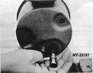
Fig. 1 Remove Stud and Union
Fig. 2 Remove Flow Control Valve and Spring
CTS-2296R Chapter 3, Page 3
PRINTED IN UNITED STATES OF AMERICA
|