|
| |
TM5-4210-229-14&P
6-18. TRANSFER CASE REPAIR (Continued).
(4)
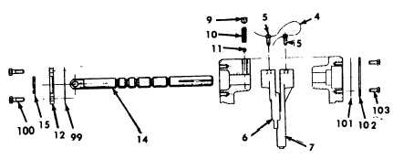
Insert the front drive shift shaft (13), the one
with 3 grooves on the shaft, into the shift shaft
hole closest to the front drive output. Slip the
shift travel limiting tube (97) onto the end of
the shaft as it emerges on the inside of the
case.
(5)
Place the forked end of the front drive shift
fork (8) (6-3/4 inches long) into the groove in
the front drive clutch.
(6) Align hub end of shift fork with the shift shaft.
Shift shaft should be inserted through the fork
and into the hole in the back of the case
housing inner wall.
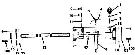
(7)
Rotate the shaft so the flat face of the eye
end of the shaft is paralleled to a line
connecting the centerline of the input shaft
with the rear output shaft centerline and with
the flat or longitudinally grooved portion (on
the rear end of the shift shaft) away from the
hole (98) for the front drive indicator switch.
Failure to do this may result in improper
switch operation.
(8)
Align the shift shaft rear most circumferential
groove under the shift fork (8) set screw hole.
Install the shift fork set screws (5) into the
fork. Torque the shift fork set screw (5) to 25
ft-lb (33.90 N.m) and lockwire (4).
(9)
Insert seal (15) into carriers (12) with lip
facing down. Install carriers (12) and gaskets
(99) on the front of the case (over the shift
shaft ends) with the seal to the outside and
torque the bolts (100) to 15 ft-lb (20.34 N.m).
(10) Install the plunger (3) into the front drive
indicator switch hole (98) with the rounded
end toward the shaft. Install the shift indicator
switch (1) with the number of washers (2)
removed in disassembly. Use a circuit tester
to test the switch operation
while shifting into and out of front drive. Add
or subtract washers (2) as necessary to make
the switch operate properly.
(11)
Install gaskets (101) and shift shaft caps
(102). Torque the bolts (103) to 15 ft-lb (20.34
N.m).
(12) Insert each detent ball (11) and detent spring
(10) into the proper bore in the top of housing.
Install each detent set screw (9) and torque
screw until it takes a force of 25 to 40 lbs
(33.90 to 54.24 N.m) to push the shift shaft
out of detent.
g.
Final assembly.
(1)
Make sure there are no loose tools, bolts, or
other foreign objects in the assembly. Rotate
all shafts (while observing through the cover
opening) with the shift shafts shifted to all
positions.
(2)
Position the cover gasket and cover by
aligning holes. Install a lockwasher on each
capscrew and coat the capscrew threads with
sealant (Appendix D, Item 47). Install
capscrews and torque to 45 ft-lb (61.02 N.m).
(3)
Install the drain and fill plugs.
(4)
Attach all applicable mounting brackets before
reinstalling the case in the truck.
(5)
Install transfer case (paragraph 4-159).
6-104
|