|
| |
TM5-4210-229-14&P
6-18. TRANSFER CASE REPAIR (Continued).
(9)
Coat the seal surface area and the splines
with Lubriplate (Appendix D, Item 34). Install
the yoke on the front of the input shaft.
Lightly coat one side of the retaining washer
(93) with sealant (Appendix D, Item 47) and
then install it onto the shaft with the coated
side facing the input yoke. Install the yoke
retaining locknut (94) and torque it to 300 ft-lb
(406.80 N.m).
(10) Temporarily install the input shaft rear cap
(16) without shims (95) and torque bolts (96)
to 25 ft-lb (33.90 N.m). Measure the gap
between the input shaft rear cap (16) and the
case housing. Select a shim stack that is 0.0
10 to 0.005 in. larger than the gap dimension
measured. Remove the cap (16) and then
install the selected shims (95) and reinstall
the cap. Coat the bolt threads with sealant
(Appendix D, Item 47), install and torque bolts
(96) to 45 ft-lb (61.02 N.m).
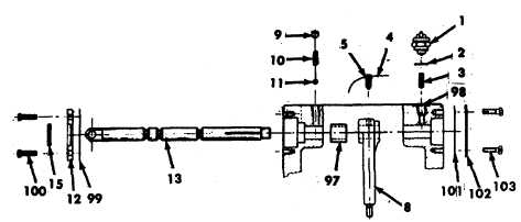
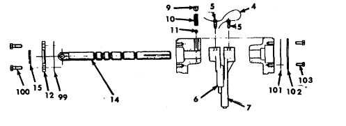
f.
Shifter shafts assembly.
NOTE
There are three shift forks used in this transfer
case. Each shift fork is a different length.
(1)
Insert the shift shaft (14), the one with 5
grooves, into the shift shaft hole next to the
input shaft until the shaft is visible through the
cover opening. Position the direct drive
clutch shift fork (6) (5-7/8 inches long) into the
groove in the clutch on the input shaft with the
long hub portion of the shift fork facing the
front of the case. Slide the shift shaft through
the shift fork just enough to
clear the underdrive shift fork (7) (7-5/8 inches
long). The underdrive shift fork (7) should be
installed at this time with the hub portion of
the shift fork facing the rear of the case and
the forked end into the groove in the clutch on
the intermediate shaft. Slide the shift shaft
through this fork and into the hole on the back
of the case.
(2)
Align the retaining screw hole on the
underdrive shift fork (7) with the rear-most
groove in the shift shaft. Install the shift fork
set screw (5) into the fork. Position the flat
face of the eye end of the shift shaft paralleled
to a line through the input and rear output
shaft centerlines in order to put the flat side in
a vertical plane on the installed case. Torque
the shift fork set screw to 25 ft-lb (33.90 N.m).
(3)
Slide the direct drive fork (6) and clutch to
position the fork set screw hole over the next
shift shaft groove and install set screw (5). To
insure
maintenance
of
fork-to-clutch
clearance, hold the two shift forks in either
clockwise or counterclockwise direction and
then torque set screw. Torque set screws (5)
to 25 ft-lb (33.90 N.m)and lockwire (4).
6-103
|