|
| |
TM5-4210-229-14&P
6-18.
TRANSFER CASE REPAIR (Continued).
(13)
Coat the seal surface and the splined
hole of the rear output companion flange with
Lubriplate (Appendix D, Item 34), then install
flange. Lightly coat one side of the retaining
washer (68) with sealant (Appendix D,
Item47) and then install the coated side next
to the companion flange. Install the locknut
(69) and torque it to 300 ft-lb (406.80 N.m).
(14)
Temporarily install the rear output shaft front
cover (35) without shims (70) and torque bolts
(71) to 25 ft-lb (33.90 N.m). Measure the gap
between the cover (35) and the case housing.
Select a shim stack that is 0.010 to 0.005 inch
larger than the gap dimension measured.
Remove the bolts (71) and the cap (35) and
then install he selected shims and reinstall the
cap. Coat the bolt threads with sealant
(Appendix D, Item 47), install and torque
bolts (7 1) to 45 ft-lb (61.02 N.m).
d.
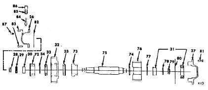
Intermediate shaft assembly.
(1)
Install the double row ball bearing (72) in the
housing bore opposite the large opening at
the rear of the case. Temporarily retain the
bearing with a bolt and washer.
(2)
Insert the alignment tool through the bearing
with the tapped end toward the inside of the
case.
(3) Put the bearing spacer washer (34) in place
onto the alignment tool on the inside of the
case. Place the underdrive driven gear (32)
and bearing assembly (33) on the alignment
tool. Insert the sliding clutch (73) into the
engaged position inside the underdrive driven
gear (32).
(4) Install the split retaining ring (74) into the
groove on the intermediate shaft (75).
(5) Insert the shaft through the large opening on
the back of the case. Align shaft with clutch
splines and engage the end of the shaft with
alignment tool. Screw the tool and shaft
together and then pull the shaft through the
bearings. Once the shaft is pulled through,
remove the alignment tool. Install the spacer
tube (30), speedometer(29), and locknut (28)
on the end where the alignment tool was
removed.
(6) Put the direct drive gear (76) onto the shaft
with the chamfered spline side toward the front
of the case so the chamfer will fit upon to the
split retaining ring (74).
(7) Install the spacer washer (77) and the roller
bearing inner race (3 1) on the shaft. Make
sure the shoulder on the race is toward the
gear to allow the cover and the bearing outer
race and roller assembly to fit over the inner
race.
(8) Install the retaining washer (78) and lock-nut
(79) on the shaft. Torque the nut (28) on the
speedometer gear end to 175 ft-lb (237.30
N.m) while restraining the nut on the opposite
end of the shaft.
(9) Torque the rear locknut (79) to 300 ft-lb
(406.80 N.m) while restraining the front output
yoke
from
turning.
6-101
|