|
| |
TM5-4210-229-14&P
6-15.
TRANSMISSION REPAIR (Continued).
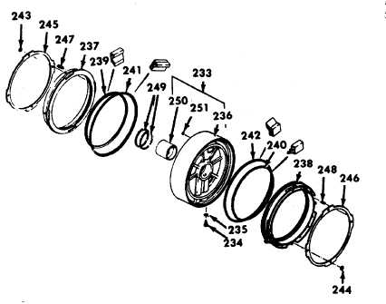
(2) Assembly.
(a) If the bushing (250) and ball (25 1) were
removed from the center support, install
new parts.
(b) Install the ball (251) and bushing (250).
Use center support bushing installer to
press the bushing into the center support.
The bushing is prebored and requires no
reaming.
ton. Compress the springs by forcing the
retainer (246) into the recess at the outer
edge of the center support. Install new
selflocking retainer rings (244) on the
ejector pins of the piston, using lockring
installer. Remove the piston (238) from the
center support (233).
(e) Grease (with oil-soluble grease, Appendix
D, Item 2 1) and install inner sealrings (239
and 240) and outer sealrings (241 and 242)
onto pistons (237 and 238). The lips of all
the sealrings must be toward the piston
cavities of the center support.
NOTE
If the pistons are not installed to the
bottom
of
their
cavities
during
installation of self-locking retainer rings
(243 and 244) proper clutch clearance
cannot be established.
(d) Temporarily place second clutch piston
(238) into the rear cavity of center support
assembly (233). Install springs (248) into
the pockets of the piston (238). Align
spring retainer (246) on the four ejector pin
bosses of the pis-
(f) Inspect the piston cavities in center
support assembly (236) for any obstruction
or foreign material. Install piston (238) into
the rear of the center support, engaging
the lug on the piston with the recess in the
support. Be sure the lips of both the inner
sealring (240) and outer sealring (242) face
the bottom of the piston cavity. Leave the
assembled third clutch piston (237) out of
the center support until final installation of
the center support assembly.
(c) Temporarily place third clutch piston (237)
in the front piston cavity of center support
assembly (233). Install springs (247) into
the pockets of the piston. Align spring
retainer (245) on the four ejector pin
bosses of the piston. Compress the springs
by forcing the retainer into the recess at the
outer edge of the center support. Install
new self-locking retainer rings (243) on the
ejector pins of the piston, using lockring
installer. Remove the piston (237) from the
center support (233).
6-72
|