|
| |
TM5-4210-229-14&P
6-15.
TRANSMISSION REPAIR (Continued).
c)
Install adjusting ring (85),flat side first, over
valve top (87). Align the adjusting ring as it
was previous to disassembly.
(d)
Depress ring (85) against spring pressure, and
install pin (86) through the holes in valve body
(90), valve stop (87) and into the slot of
adjusting ring (85). Be sure the adjusting ring
is aligned with the pin as it was before
removal. Adjusting ring tool may be used to
properly locate the adjusting ring.
c.
Control value repair.
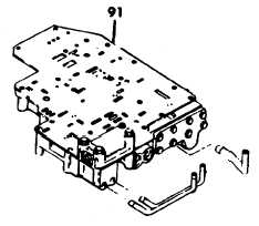
(1) Disassembly.
The valve body assembly (91) contains a number
of springs, some of which are similar and can be
mistakenly interchanged. If springs are not
reinstalled in the same locations from which
removed, the calibration of valve body functions
will be lost. For these reasons, it is recommended
that each spring, at removal, be tagged with its
item number and utilize valve body parts tray set.
6-57
|