|
| |
TM5-4210-229-14&P
6-15.
TRANSMISSION REPAIR (Continued).
(6)
End play check
(a) Support the converter assembly on the
converter cover (pump hub upward). Place
converter
end
play
gauge
into
the
converter pump hub. Hold the center screw
of the gauge downward and tighten the nut
until the gauge is securely held in the
converter turbine hub. Do not overtighten.
(b) Install
the
dial
indicator.
Adjust
the
indicator bracket so the dial is in contact
with the top of the center screw. Set the
dial to read zero.
(c) Using both hands, lift the center screw as
far as possible. Record dial indicator
reading (this is dimension B). Select the
proper size spacer.
(d) It is not necessary to disassemble the
complete converter to install the selected
spacer.
Remove
only
those
items
necessary to install the spacer.
(e) Disassemble the converter by following
paragraph a. (2) steps (b), (c) and (i).
(f) Install the selected spacer into the turbine
hub.
(g) Assemble
the
converter
by
following
paragraph a. (5), (j) and (q). The end play
may be rechecked as in a. (6). Proper end
play is any dimension between 0.001 and
0.025 inch (0.03 and 0.64 mm).
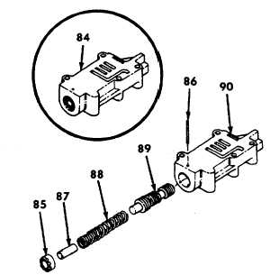
b. Modulated lockup valve (84) repair.
(1) Disassembly
(a) Mark adjusting ring (85) to indicate its
position in relation to pin (86).
(b) Depress ring (85) against spring pressure,
and remove pin (86).
(c) Remove adjusting ring (85), valve stop
(87), spring (88), and valve (89) from valve
body (90).
SPACER CHART
Dimension B
User Parts No.
Color
inches (mm)
Less than 0.0177
Use no spacer
(0.449)
0.0177-0.034
6837429
Gold
(0.449-0.86)
0.034-0.049
6837430
Silver
(0.86-1.24)
0.049-0.062
6837431
Plain
(1.24-1.57)
0.062-0.079
6837432
Black
(1.57-2.00)
0.079-0.093
6837433
Copper
(2.00-2.369)
(2) Assembly
(a) Install valve (89( smaller diameter first, into
valve body (90).
(b) Install spring (88). Install valve stop (87)
undrilled end first, into spring (88).
6-56
|