|
| |
TM5-4210-229-14&P
6-15. TRANSMISSION REPAIR (Continued).
(t) Flatten the corners of lockstrips (69) and
remove eight bolts (70) and four lockstrips
from converter pump hub (67).
(u) Remove hub (67) and gasket (71) from
pump (54). Remove sealring (72).
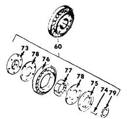
(3) Stator repair.
NOTE
Do not disassemble the stator assembly
(60) unless replacement of stator thrust
washer (73), rivets (74) or washer (75) is
necessary. If stator (76) or cam (77) is
cracked
or
damaged,
replace
the
complete stator assembly (60).
A hydraulic press having a minimum
capacity of five tons, an adjustable
table, and a pressure gouge to assist in
determining
rivet
staking
load
is
required to repair the stator assembly
(60).
(a) Place the stator assembly (60) in a drill
press, formed rivet side up.
(b) Using a 3/8 inch drill, align and drill the
rivet, removing the formed head.
(c) Place
base
plate
under
the
stator
assembly. Be sure the holes in the base
plate are under the rivet heads. Place top
plate on top of the stator assembly (60).
(d) Install the 5/8-11x3.25 inch bolt to hold the
two plates together. Torque the bolt to 60
ft-lb (81 N.m).
(e) Place fixture stand on a hydraulic press.
Install rivet remover pin into the fixture
head. Tighten the tool retainer thumb
screw.
(f) Place the stator assembly (60) with base
and top plates, onto the fixture stand,
drilled rivet side up.
(g) Align the rivet remover pin with the drilled
rivet and press the rivet (74) from the
stator assembly (60). Repeat the above
process for each rivet (74).
(h) Remove the retaining bolt and top plate.
Separate thrust washer (73), side plate
washer (75), two cam washers (78), and
cam (77) from stator (76).
(i) Inspect the stator and cam for cracks, rivet
holes or burrs or swelling. Deburr as
required. If cam or stator is cracked or
distorted, replace the stator assembly (60).
(j) Clean the stator assembly components.
Assemble cam (77) and stator (76) with the
roller pocket. Install cam washer (78) one
on each side of the stator. Install side plate
washer (75) and thrust washer (73).
(k) Align the six rivet holes and insert six new
1/4x1.94 inch rivets (74) into the stator
assembly from the rear to the front of the
stator.
(l) Pace the stator assembly (60) on base
plate. Be sure the rivet heads rest on the
base plate, between clearance holes.
Install top plate and the 5/8-11x3.25 inch
retaining bolt. Strike the top plate with a
rubber mallet to seat components. Torque
retainer bolt to 60 ft-lb (81 N.m).
6-51
|