|
| |
TM5-4210-229-14&P
6-13. FLYWHEEL, CRANKSHAFT, AND MAIN BEARING MAINTENANCE (Continued).
(3) Mill or grind surface of the NEW cap to
dimension plus 0.002 in (0.05 mm).
NOTE
0.002 in (0.05 mm) is added to dimension to
allow enough stock for a finish cut on surface
after the cap and bearing have been fitted to
the crankcase.
The bearing cap must be located on its
machined side when grinding surface to hold
squareness.
(4) Clamp the OLD bearing cap to a surface
plate.
(5) Place a drill rod of any size from 1/4 to 1/2
inch (6 to 13 mm) on the inside of the cap
(against notched side). Measure this dis-
tance with a micrometer and record the
reading.
(6) Measure the diameter of the drill rod shank
and add this reading to the reading taken in
step (5) above. This will be dimension A.
(7) Measure dimension A of the NEW bearing
cap in the same manner as described in
steps (3), (5), and (6) above.
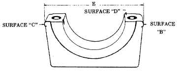
(8) Subtract dimension A of the OLD cap from
dimension A of the NEW cap and record
the difference. Mill or grind this amount
from surface C of the new cap. Dimension A
of both caps will now be equal.
NOTE
Surface C must be held square with surface D
and parallel to the bearing bore.
(9) Mill or grind surface B of the new cap until
the dimension E 6.050-6.052 in. (153.67-
153.72 mm) shown from surface C to B is
obtained.
NOTE
Surface B must be held square with surface D
and parallel to the bearing bore.
c. Main bearings installation.
(1) Install a new bearing in a new bearing cap or
the original bearing in the original bearing
cap, as called for.
(2) Bearing clearance check.
NOTE
Do not turn the crankshaft during this procedure.
(a) Clean the bearing surface and the ex-
posed half of the crankshaft journal. Be
sure these surfaces are free of oil.
(b) Place a suitable length of 0.010 inch
(0.254 mm) virgin lead wire or a piece of
plastigage (Appendix D, Item 40a)
across the bearing surface.
(c) Install the bearing cap and torque the
cap screws to 115 ft-lb (155 N.m).
(d) Remove the bearing cap. When virgin
lead is used, measure the crushed
thickness with a micrometer and re-
cord the results. When plastigage is
used, the flattened plastic material will
be found adhering to either the bearing
or the crankshaft. Do not remove the
plastigage. Determine bearing clear-
ance by comparing the width of the flat-
tened plastic with the graduations on
the envelope.
6-40
|