|
| |
TM5-4210-229-14&P
6-6. CYLINDER HEAD AND VALVES MAINTENANCE (Continued).
u. Lubricate bolt threads, bolt head seating areas
and washers with clean lubricating oil (Appen-
dix D, Item 36).
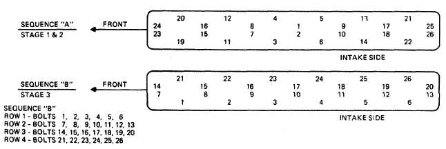
v. Torque bolts in three stages:
Stage 1: Following sequence "A" torque bolts
to 110 ft-lb (150 N.m).
Stage 2: Following sequence "A" torque bolts
to 155 ft-lb (210 N.m).
Stage 3: Following sequence "B" torque bolts in
rows, 165 ft-lb (225 N.m).
CAUTION
Do not back bolt off, pull up to torque level
indicated. Check the two end rocker arms
for freedom of motion after torquing first
stage.
Do not adjust valves with the engine
running. Severe damage can result from
inserting feeler gauge between valve and
valve lever due to close clearance of valve
piston.
w. Valve lash adjustment.
NOTE
Valve lash may be adjusted as a separate
operation without cylinder head and valve
lever removal, disassembly, cleaning, inspec-
tion or repair.
All valves are adjusted by cranking the engine
only twice.
Perform valve lash adjustment with the engine
warm which means any temperature above
freezing.
(1) Turn the crankshaft until the number one
piston is on the compression stroke and the
timing pointer on the front cover is in line
with the top dead center mark (pin) on vib-
ration damper or flywheel.
NOTE
Be sure that the number one piston is on the
compression stroke by turning both push rods
by hand to determine that both valves are
closed. Valves are closed when push rods are
loose and can be turned easily.
(2) Six valves are adjusted when the number 1
piston is at top dead center (compression)
and the remaining six are adjusted when the
number 6 piston is at top dead center (com-
pression). Odd numbered valves are intake
valves; and even numbered valves are ex-
haust valves.
(3) Valve tappet clearance (lash) is 0.025 inch
(0.64 mm) for intake valves and exhaust
valves.
CAUTION
When tightening head bolts, place a 0.005 inch
(0.127 mm) feeler gauge between the outside
brackets and the rocker levers to prevent
binding.
6-13
|