|
| |
TM5-4210-229-14&P
5-12.
ALTERNATOR REPAIR (Continued).
ASSEMBLY
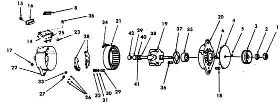
a.
Install bearing (42) on the inner race of the bearing
(19).
b.
Press on new slip ring assembly (39, 40,and 41)
making sure the slot lines up with the slot in the
shaft. The new slip ring assembly should be
pressed on the shaft with enough pressure to
prevent the insulation washer (41) from turning.
c.
Solder the rotor coil leads (38) to slip ring assembly
using a heat gun and solder (Appendix D, Item 53).
d.
Place slip ring end of rotor shaft (19) into an arbor
press. Install the rotor and drive end housing (20)
by pressing the housing and bearing (35) on rotor
shaft.
e.
Install the stator (21) on the slip ring end housing
(22) and align bolt holes in stator (21) with housing
(22).
f.
Install three stator terminals (24) on the terminal
board studs (25) and secure with lock nuts (23).
NOTE
Spray the terminal body assembly with sealant
(Appendix D, Item 41).
g.
Support the slip ring end housing (22) on an arbor
press. Slip the rotor (19) to the drive end housing
(20) through the stator (2 1) and into the slip ring
end of the housing.
h.
Install three through bolts (18), lock nuts (17).
i.
Install the regulator (8) and brushes (36) in the
housing (22).
j.
Install jumpers (24) using nuts (9 and 10).
k.
Push and pin the brushes (36) in place.
l.
Install regulator brush holder housing assembly (13)
and install four brush housing screws (14). Coat
with Loctite (Appendix D, Item 27).
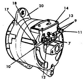
m. Install nuts (9 and 10) output terminals (11 and 12)
and connect diode lead (7).
n.
Install fan spacer (6), drive key (5), fan (4), and
pulley (3) to the regulator (8).
o.
Install washer (2) and shaft nut (1).
p.
Install alternator (paragraph 4-84).
5-30
|