|
| |
TM5-4210-229-14&P
Table 2-1. Twin Agent System Controls and Indicators (Continued).
Twin Agent 4x4 Firefighting Truck
(Refer to Figure 2-1)
Key
Control or Indicator
Function
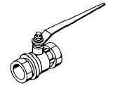
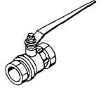
5
Master Control Valve
The Master Control Valve is a quarter turn valve and
is located in the high pressure line. The control valve
pressurizes the system and may be activated from a
location at the rear of the unit or from inside the cab.
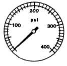
6
Test Gauges
The Test Gauges indicate regulated nitrogen pressure
in the agent tanks.
7
Test Valves
The Test Valves are located in the low pressure line
between the main regulators and the check valves.
Their function is to allow the reduced pressure system
to be tested under pressure, without the agent
tanks being charges.
8
Dry Chemical Tank Drain Cap
The Dry Chemical Tank Drain Cap is removed when
inspecting or cleaning the agent tank.
To remove cap, turn counterclockwise.
2-4
|