|
| |
TM5-4210-229-14&P
4-170.
BRAKE DRUM MAINTENANCE (Continued).
REMOVAL
a.
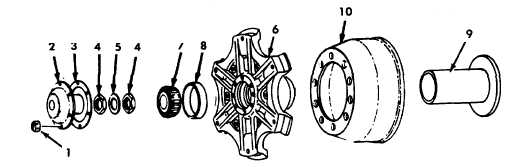
Remove eight nuts (1), grease cap (2) and gasket
(3).
b.
Remove two bearing adjustment nuts (4) along
with washer (5).
c.
Tap on cast wheel hub (6) using a rubber mallet
until wheel works loose and outer cone bearing (7)
and bearing outer cap (8) can be slid off spindle
(9).
d.
Remove wheel hub (6) and drum (10).
SERVICE
NOTE
The brake drum is removed with the hub. Brake
drums that are otherwise in good condition can
be turned in a lathe. However, it must be re-
membered that the recommended remachining
or rebore limit for brake drums with a diameter
over 14 inches (355 mm) may not be increased
more than .080 inch (2.03 mm) diameter (total
cut) and discarded at .120 inch (3.05 mm) over
normal diameter.
The dimension located on the drum is discarded
dimension. Never remachine drums to maximum
wear or discard diameter.
To recondition a brake drum in a lathe, the drum
must be remounted so that it is centered.
d. Grind the finished surface if grinder is available or use
emery cloth (Appendix D, Item 13) on a straight piece of
wood and polish the drum friction surface.
e. Brake drums should be cleaned thoroughly with a steam
cleaner or hot water.
INSTALLATION
a. Pack bearing (7) with grease (Appendix D, Item 20).
b. Carefully slide drum (10) and hub (6) onto spindle (9).
c. Slide bearing outer cap (8) and bringing outer cone (7)
onto spindle and push into position in wheel hub (6).
d. Install one bearing adjusting nut (4) and tighten by hand,
rotate wheel hub (6) and take up slack by torquing
adjusting nut (4) to 50 ft-lb (67.8 N.m).
e. Back off nut approximately one quarter to one-third turn
and install washer (5) and second nut (4).
a.
Install brake drum on lathe.
b.
Use proper size cone to provide accurate centering.
c.
Turn drum, taking only light cuts and remove just
enough material to clean up drum.
f. While securely holding inner nut (4) with a wrench,
torque outer nut (4) with another wrench to 150 ft-lb (203
N.m). Check for free movement.
g. Install gasket (3) and grease cap (2) with eight nuts (1)
and torque nuts to 15 ft-lb (20.1 N.m).
h. Install tire rim assembly (paragraph 4-162).
4-187
|