|
| |
TM5-4210-229-14&P
4-163. TIRE REPLACEMENT (Continued).
NOTE
Recommended vehicle tire mounting and
inflation procedures are especially important
with radial tires. Failure to follow these
procedures can cause bead deformation due to
incorrect bead seating. Bead deformation may
lead to chafing, lower sidewall and bead area
packing, eccentric wear, ride vibratin and
non-retreadable castings.
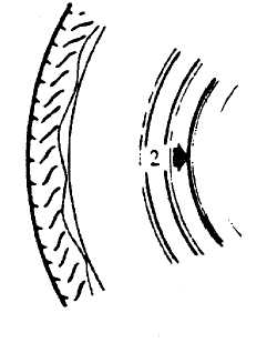
d. Install valve core and inflate to proper pressure.
Check the locating rings (2) of the tire to be sure
they show around the rim flanges on both sides.
e. Check the spacing between the rim flange and one
of the three lower sidewall rim line rings while the
tire
is
laying
flat
to
verify
bead
seating.
Measurements must be taken each 90 degrees
around the circumference of the rim flange.
NOTE
If the spacing is uneven around the bead from
side to side, repeat steps a through c, then
recheck.
Before re-installing the rims, remove any build
up of corrosion on the rim mounting surface
and disc mounting surface by scraping and
wire brushing. Installing rims without good
metal-to-metal
contact
at
the
mounting
surfaces can cause lug nuts to loosen. This
can lead to a rim coming off while the vehicle is
moving, causing loss of control.
f. Place the tire rim assembly in position on the hub
and install the lug nuts snugly in a criss-cross
pattern to minimize runout.
NOTE
Lateral runout should not exceed 0.125 inch
(3.18 mm) on the front wheels and 0.187 inch
(4.76 mm) on the rear wheels.
g. Turn the wheel until one nut is at the top of the bolt
circle, then tighten evenly and alternately according
to a torque of 190-210 ft-lb (258-285 N.m).
h. Inflate tire(s) to 80 psi (551.6 kPa).
i. Lower vehicle.
4-179
|