|
| |
TM 5-4210-229-14&P
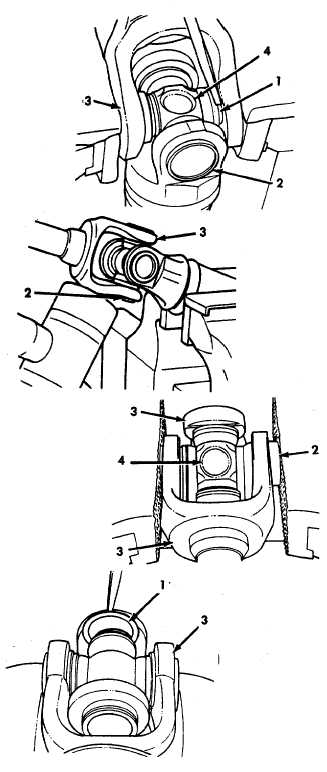
4-120. FLEXIBLE COUPLING REPLACEMENT (Continued).
REMOVAL
a. Place the universal joint in a vise. Remove the
snap rings (1), retaining the bearings (2) in the
yoke (3).
b. Place the shaft assembly in a vise. Tap the yoke
(3) with a soft hammer beside the bearing (2)
that is being removed. The bearing should
come out. If the bearing does not come out,
place the bearing in a vise. Use copper jaw
covers on vise. Tap the yoke away from the
bearing.
c. Remove the spider (4) after the bearings (2)
have been removed.
INSTALLATION
NOTE
Make certain parts are clean before assembly.
a. Rest yoke (3) on hard surface. Tap one bearing
(2) part way into yoke with a soft hammer. Be
certain bearings (2) are straight in yoke (3).
b. Insert spider (4) through the opposite hole,
without bearing, and swing it into place and
down into the partially installed bearing (2).
c. Turn assembly over and tap the opposite bearing
part way into the yoke. Be certain to start
bearing straight in yoke (3).
d. Place yoke in vise with bearings against jaws of
vise. Tighten vise slowly and the bearings will
be pressed into the yoke.
e. After pressing bearing into yoke (3), the spider
may be off center in yoke. This is desirable
because it permits installation of snap ring (1)
on the side with the most clearance. Install
snap ring (1).
f. After the first snapring (1) is in place, turn
assembly over. The bearing with snapring
installed should be on the bottom. Rest yoke on
vise and strike bearing which is on top. This will
seat both bearings. Snaprings should rest
against inside milled surface of yoke. Install
remaining snapring (1).
g- Bearings (2) must move freely. If tight, tap yoke
until free.
h. Install steering column (paragraph 4-119).
4-132
|