 |
|||
|
|
|||
|
|
|||
| ||||||||||
|
|
 TM5-4210-224-14&P
6-11.
FRONT COVER MAINTENANCE. (Continued)
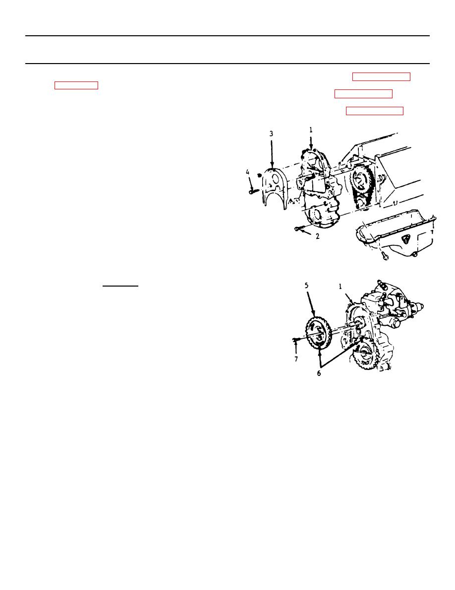
e. Apply a 3/16 inch (5 mm) bead of RTV sealant
m. Install torsional damper (paragraph 6-10).
surface that mates against the oil pan.
n. Install water pump (paragraph 4-78).
f. Position the front cover (1) to the engine and
o. Service cooling system (pararaph 4-72).
install the attaching bolts (2).
g. Torque the front cover to block bolts to 33 ft-lbs
(45 N.m) and the oil pan bolts to 84 ft-lbs (10 N-
m).
h. Install the baffle (3) and torque the baffle bolts
(4) to 33 ft-lbs (45 N-m).
i. Align the scribe marks on the front cover (1) and
injection pump.
j. Install the injection pump with the nuts and
torque to 31 ft-lbs (42 N-m).
k. Install the injection pump driven gear (5) making
sure the timing marks (6) on the cam gear and
the pump gear are aligned.
CAUTION
Measure the clearance between the
injection pump gear and baffle.
A
minimum of 0.040 inch (1.0 mm)
clearance between the gear and baffle
is necessary to prevent damage or
wear.
l. Install the injection pump gear bolts (7) and
torque to 17 ft-lbs (23 N-m).
6-15
|
|
Privacy Statement - Press Release - Copyright Information. - Contact Us |
