 |
|||
|
|
|||
|
|
|||
| ||||||||||
|
|
 TM 5-4210-224-14 & P
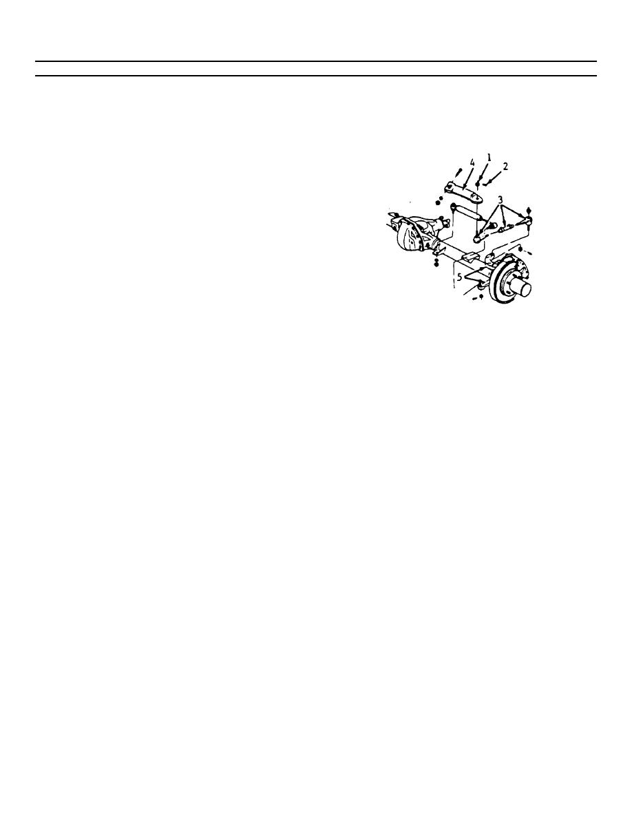
4-224. CONNECTING RODS REPLACEMENT. (Continued)
the straight ahead position, loosen the adjuster
d. Install the inner connecting rod (3) ball stud
tube clamps on the connecting rod (3) and turn
short end to the pitman arm (4) making certain
the adjuster tube to bring the gear back on high
the seal is on the stud.
point.
e. Install the castellated nut (1) to the inner
connecting rod ball stud and torque to 89 ft-lbs
(120 N.m).
f. Advance the nut to align the nut slot with the
cotter pin hole and install a new cotter pin (2) of
the correct size.
NOTE
Never back the nut off to align the
cotter pin hole.
g. Install the outer connecting rod ball stud to the
steering knuckle (5).
h. Install the castellated nut (1) to the outer
connecting rod ball stud and torque to 89 ft-lbs
(120 N.m).
l. Install the adjuster tube clamp bolts. Before
i. Advance the nut to align the nut slot with the
tightening the clamp bolts, be sure the following
cotter pin hole and install a new cotter pin (2) of
conditions have been met:
the correct size.
(1) The clamps must be positioned between
NOTE
the locating dimples at either end of the
Never back the nut off to align the
adjuster tube.
The clamps must be
cotter pin hole. The connecting
positioned within the angular travel
rod ends to the pitman arm and
shown.
steering knuckle must be in correct
(2) Both inner and outer connecting rod ends
relationship to each other after
must rotate for their full travel. The
adjustment, within +/2 degrees.
position of each connecting rod end must
be maintained as the clamps are
j. Set the front wheels in the straight ahead
tightened to ensure the free movement of
position.
each joint.
k. With the front wheels set straight ahead, check
the position of the mark on the wormshaft
designating steering gear high point. This mark
m. Torque the adjuster tube bolts to 40 ft-lbs (54
should be at the top side of the shaft at the 12
N.m).
o'clock position and lined up with the mark in the
n. Lower the vehicle.
coupling lower clamp. If the gear has been
moved off high point when setting the wheels in
4-312
|
|
Privacy Statement - Press Release - Copyright Information. - Contact Us |
