 |
|||
|
|
|||
|
|
|||
| ||||||||||
|
|
 TM5-4210-224-14&P
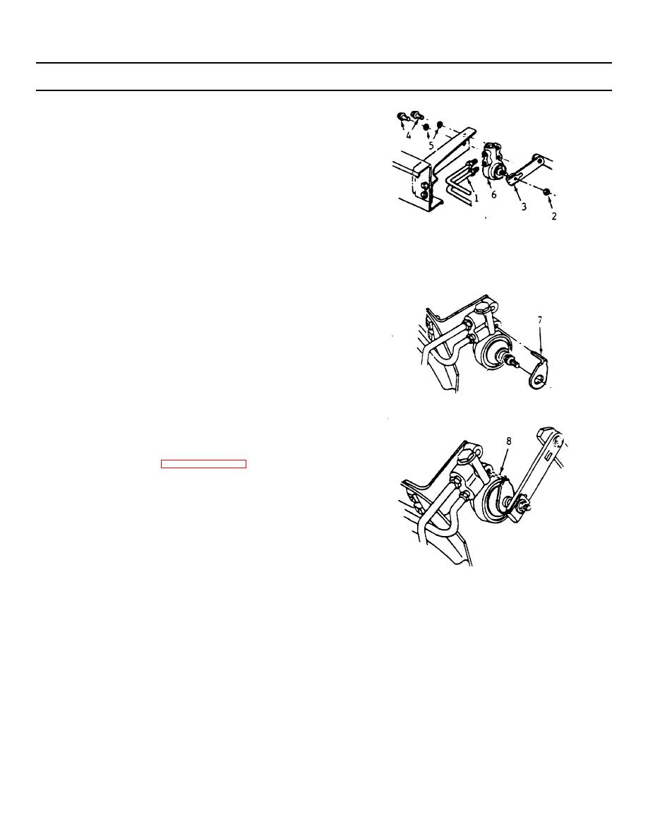
4-211. HEIGHT SENSING BRAKE PROPORTIONING VALVE REPLACEMENT.
(Continued)
INSTALLATION
a. Position the valve (6) on the mounting bracket
and install the washers (5) and bolts (4).
b. Rotate the valve shaft to permit the installation
of the adjustment gauge (7).
NOTE
The center hole of the adjustment
gauge must seat on the "D" shape
of the valve shaft.
c. Position gauge tang, so that it seats in the valve
mounting hole.
NOTE
Do not drive lever assembly on
valve shaft by using nut or proper
valve setting may be disturbed.
d. Install the lever (3).
e. Install the nut (2) and torque to 89 in-lbs (10 N-
m).
f. Sever the tang (8) on the adjustment gauge.
g. Install the brake pipes.
h. Bleed the brakes (paragraph 4208).
i. Remove the jack stands and lower the vehicle.
j. Test the brakes.
NOTE
If a front wheel lock up is
experienced when the vehicle is
being operated near the maximum
Gross Vehicle Weight Rating with
a lower than desired brake
application, the valve adjustment
should be checked.
4-292
|
|
Privacy Statement - Press Release - Copyright Information. - Contact Us |
