 |
|||
|
|
|||
|
|
|||
| ||||||||||
|
|
 TM5-4210-224-14& P
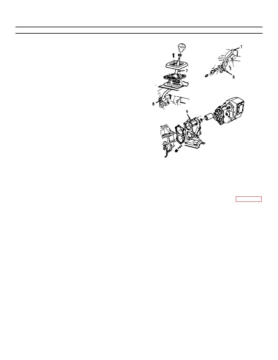
4-200. TRANSFER CASE REPLACEMENT. (Continued)
g. Disconnect the shift lever rod (7) from the shift
rail link (8).
h. Support the transfer case with a suitable stand
and remove the bolts (9) attaching the transfer
case to the transmission adapter.
i. Move the transfer case to the rear until the input
shaft clears the adapter, then lower the
assembly from the vehicle.
INSTALLATION
a. Support the transfer case in a suitable stand and
position the case to the transmission adapter.
b. Install bolts (9) attaching case to adapter and
torque to 45 ft lbs (62 N-m).
c. Remove the stand.
d. Install the shift lever rod (7) to shift rail link (8)
and torque nuts to 12 ft-lbs (17 N-m).
NOTE
Connect the shift lever to the
g. Install crossmember support and skid plate and
transfer case if the shift lever was
torque to 46 ft-lbs (63 N-m).
removed.
h. Install the drain plug (1) and torque to 32 ft-lbs
(44 N-m).
e. Connect the front propeller shaft to the transfer
case front output flange or yoke and torque to
i. Fill the transfer case to within one inch of fill
75 ft-lbs (102 N-m).
plug (1) with Dextron II lubricant (Appendix D,
Item 22).
f. Connect the rear propeller shaft to the transfer
case rear output yoke and torque bolts to 30 ft-lbs (40 N-
NOTE
m).
Capacity of the transfer case is 5.2 pints.
j. Install the fill plug and torque to 32 ft-lbs (44 N-
m).
k. Lower the vehicle.
4-272
|
|
Privacy Statement - Press Release - Copyright Information. - Contact Us |
