 |
|||
|
|
|||
|
|
|||
| ||||||||||
|
|
 TM 5-4210-224-14&P
1-9. LOCATION AND DESCRIPTION OF MAJOR COMPONENTS. (Continued)
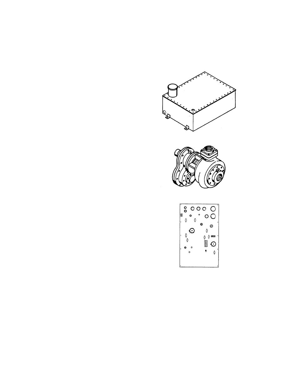
(7) Water Tank.
The water tank
holds 250 gallons.
Baffle
partitions in the tank prevent
surges on side sway while the
truck is maneuvering with the tank
filled or partially filled. The tank
is provided with a top fill tube,
gasket and a cover. The fill tube
is designed so a 21 inch hose can
be placed in the opening so the
tank can be filled without the hose
being held by the operator. The
fill opening also includes a
removable strainer to prevent
foreign matter entering the tank
during filling operations. The tank
can also be filled by pressure
FIGURE 1-8. WATER TANK
through the 3 inch fire pump
suction inlet.
(8) Fire Pump. The pump is a high-
speed, bronze-fitted, single stage
centrifugal type, with volute
discharges. It can operate from
either draft, hydrant or water tank.
The pump is designed to operate
FIGURE 1-9. FIRE PUMP
at 250 GPM @ 150 PSI.
(9) Street Side Pump Panel. the
street side pump panel is located
on the left side of the truck.
Pump pressure and suction
gauges are connected to the
pump manifold. One 2i inch and
two 1 1/2 inch discharge gauges
are connected to the hose line
side of each of the discharge
valves and pre-connects. The
gauges are flush mounted of the
glycerin filled type, and operate in
temperatures as low as -25 .
F
(13.8 ). The panel is illuminated
C
for night operation.
FIGURE 1-10. STREET SIDE PUMP PANEL
1-9
|
|
Privacy Statement - Press Release - Copyright Information. - Contact Us |
