|
| |
TM 5-4210-220-34
2-12.
PUMP DRIVE AND PTO - Continued
(5)
Inspect clutch discs (39 and 40). Discard any that show signs of overheating. Using a vernier caliper,
measure the thickness of each clutch disc. Discard any that do not fall within specification listed below.
#
Item
ThicknessTolerances
39
Opposing Clutch Disc
.068 .070 in. (1.73 1.78 mm)
40
Bronze Clutch Disc
0605 .063 In. (1.54 1.6 mm)
(6)
Inspect bearings, shafts, and gears as detailed in para 2-7. Make sure oil passage in drive shaft (30) is
not clogged.
(7)
Inspect companion flange splines, seal area, and mounting flange.
(8)
Inspect bearing covers (18 and 29) for cracks, warping or any other damage that may cause oil leaks.
c.
Assembly
NOTE
Lubricate seals and bearings using petroleum jelly (item 21, Appendix B) prior to assembly.
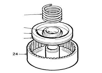
(1)
Assemble spider gear assembly as detailed
in the following steps.
(2)
Lubricate block vee rings (33 and 34) using
petroleum jelly (item 21, Appendix B) and
install onto piston (35). Make sure the
sealing lips of the block vee rings are facing
away from the spring seat.
(3)
Install piston assembly (35) into spider gear
assembly (24). Use extreme care so as not
to damage the block vee rings (33 and 34)
during installation. Twist piston assembly
into spider gear assembly to ensure piston is
fully seated.
(4)
Install spring (36) into spring seat of piston
(35).
(5)
Install retainer (37) onto spring (36) and compress using hand pressure. Lock into position using lock
ring (38).
(6)
Install one opposing clutch disc (39) and then install one bronze clutch disc (40). Continue to install
clutch discs in this staggered manner until all 14 clutch discs are installed. Make sure a bronze clutch
disc is installed last.
(7)
Install clutch stop spacer (47) and lock into position using lock ring (41). Set assembled spider gear
assembly (24) aside.
(8)
Press bearing (22) onto drive shaft (30). Make sure bearing is fully seated against mounting shoulder.
Lock bearing into position by installing lock ring (23).
2-73
|