|
| |
TM 5-4210-220-34
3-8.
ENGINE.
3-8.9
Piston, Liner, Rings, Rod and Rod Bearings.
(3)
Block counterbore depth must range from either 0.4755 0.4770 in. (12.077 12 116 mm) or 0.4905 0 4950 in.
(12.459 12.497 mm) and must not vary more than 0.0015 in. (0.0381 mm) in depth around the
circumference.
(4)
No two adjacent block counterbores may range in depth more than 0,001 in. (0.25 mm) when gaged along
the longitudinal cylinder block center line.
(5)
A replacement cylinder liner Is classified according to the flange thickness to control the distance from the top
of the liner to the top of the cylinder block. A cylinder liner with a flange thickness of 0.3100 0.3109 in.
(7.874 7.897 mm) (C1) has the part number etched on the lower portion of the bottom half of the liner. A liner
with a flange thickness of 0.3110 0.3120 in. (7.899 7.925 mm) (C2) has the part number etched on upper
portion of the bottom half of liner. Both liners have the same part number.
(6)
Do not install cylinder seals in engine block at this time.
(7)
The original liners must be installed into original hole location in block if liners are reused. Similarly original
inserts or replacement ones of same thickness should be installed into each corresponding counter-bore and
related liner.
(8)
Install insert and cylinder liner into each cylinder bore of block. Do not use excessive force to install liner.
Hand push liner into cylinder block until liner rests on insert.
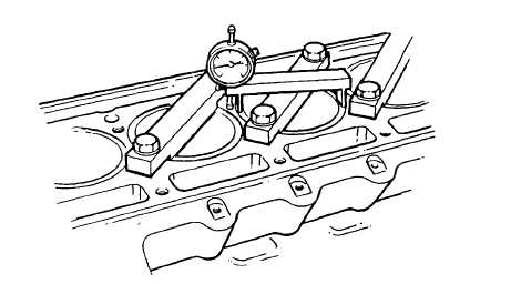
(9)
Clamp each liner in place with hold down clamp J24565-02. Tighten bolts to 50 ft lb (68 Nm).
(10)
Measure distance from the top of the liner to the top of the block with dial indicator J24898. The liner must be
0.0418 0.0482 in. (1.062 1.224 mm) below the top of the block and the difference in depth between any two
adjacent liners when measured along the cylinder longitudinal centerline must not exceed 0.0015 in. (0.038
mm). If the above limits are not met, install a different thickness insert or install liner in another cylinder bore
and recheck height, or install new replacement cylinder liner and recheck height.
3-168
|