|
| |
TM 5-4210-220-34
3-8.
ENGINE Continued
a.
Balance Weight Cover Removal
(1)
Remove water pump as detailed In para. 2-19.9.
(2)
Remove the fan clutch support (1) by removing the four mounting capscrews and lockwashers. These
capscrews are two different sizes and lengths. Note location to ensure proper assembly.
(3)
Remove the capscrews, washers, and lockwashers, that secure the balance weight cover (2) to the front end
plate (4) and the cylinder block. To make assembly easier, make a sketch of the balance weight cover and
the position of each different size capscrew.
(4)
Tap the ends of the cover with a soft-faced hammer to loosen it and remove cover (2) from the end plate (4).
(5)
Remove all traces of gasket (3) from the balance cover (2) and end plate (4).
b.
Water Pump Drive Gear Removal (1) Remove balance weight cover as detailed in a. preceding.
(2)
Drain oil from engine crankcase into a suitable container.
(3)
Remove the oil pan as detailed in para. 2-19.11.
(4)
Block the crankshaft between the crankshaft throw and the cylinder block to prevent rotation of the engine,
and loosen the retaining nut (1) at front end of the camshaft.
(5)
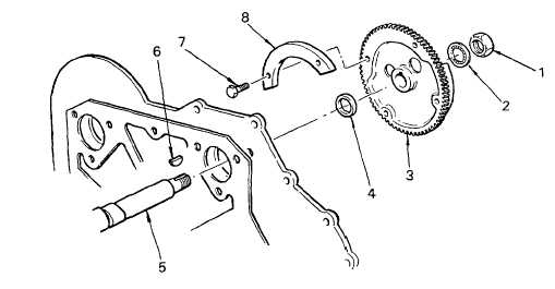
Remove the nut (1) and the internal tooth lockwasher (2) from the front end of the camshaft (5).
(6)
Attach puller J24420-A to the water pump drive gear (3). Use adapter J7932 between the end of the
camshaft (5) and the puller screw to protect the end of the camshaft. Tighten the puller screw and remove
the water pump drive gear.
(7)
Remove the woodruff key (6) and the spacer (4) from the end of the camshaft (5).
(8)
Separate the counterweight (8) from the water pump drive gear (3) by removing the capscrews (7).
3-131
|