|
| |
TM 5-4210-220-34
2-10.
PUMP BODY - Continued
(4) Tag and disconnect wires to hose reel blower.
(5)
Remove all ties attaching water and air pressure lines and wiring to pump body components.
(6) Tag and remove pressure lines from water gages and air controls on structural panel Also detach pump
tachometer drive cable.
(7)
Remove throttle and stop controls for APU as detailed m TM 5-4210-220-12.
(8)
Tag and remove auxiliary cooler hoses to control valve on structural panel.
(9)
Tag and unplug foam and water tank level monitor harnesses.
(10) Tag and remove engine coolant hoses to auxiliary cooler.
(11) Disconnect tank fill and hose reel hoses from discharge manifold valves.
(12) Tag and remove foam hoses to metering valve .
(13) Remove victualic coupling and disconnect turret discharge pipe, rear discharge, 2 1/2 in. suction pipe and
pump discharge from discharge and suction manifolds.
(14) Remove tie rod linkage from valve.
(15) Drill out and remove lockbolts (para. 2-7) attaching angles to each side of pump body. Remove both angles.
(16) Remove clamp that attaches 2 1/2 in. suction pipe to frame.
(17) Drain priming tank by opening small valve on pump primer.
(18) Disconnect priming reservoir hoses at priming tank.
(19) Detach winterization system fuel pump and filter and fuel lines from pump body.
(20) Detach PTO manual shutoff valve from left side of pump body. Do not remove hoses.
(21) Disconnect shop air connection at air drier.
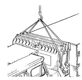
(22) Position hoist over pump body and rig up
lifting slings to body as shown.
(23) Remove four bolts and nuts attaching pump
body to frame.
When hoisting, ease the pump body up
slowly Be sure all air lines and hoses
have been disconnected properly and
the pump body does not interfere with
chassis mounted components.
(24) Carefully lift pump body clear of truck frame
and hose body and place it on the floor.
2-35
|