|
| |
TM 5-4210-220-34
3-8.
ENGINE - Continued
3-8.3
Blower - Continued
NOTE
If the blower drive shaft spring has been removed in error, compress the spring and force it into the drilled
hole opposite the tachometer drive square hole. This operation must be done on a press. To check for
proper assembly, hold the spring and shaft assembly vertically by the spring. Weight of the shaft cannot
allow the spring to come out of the drilled hole. A simple installation tool can be made from a 0.500 in.
(12.7 mm) diameter piece of steel stock.
(8)
Remove the shaft with the tool and rotate
the lobes of the blower in 90 deg.
increments, reinserting the alinement tool
and repositioning the blower, as necessary.
Check the alinement at 90 deg. increments
through the full 360 deg. of blower rotation.
(9)
If it is not possible to position the blower so
that the tool can be removed and reinstalled
without drag in all positions, repeat step 8.
However, this time try to achieve a
condition in which the shaft can be
removed with minimum drag in the two
worst positions.
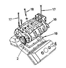
(10) With the shaft in place and the blower
properly alined, tighten the blower-to-block
end plate capscrews (17) to 45 ft lb (61
Nm). Tighten the blower housing-to-block
side angle capscrews (18) uniformly to 35 ft
lb (47 Nm) in 5 ft lb (7 Nm) increments.
(11) Recheck the torque of the blower-to-block end plate capscrews (17) and tighten as necessary.
(12) Install the blower driveshaft snap ring. The notch in the tool provides sufficient clearance for the installation
of the snap ring with needle-nose pliers. Installing the snap ring with the alinement tool in place will prevent it
from being inadvertently dropped into the engine gear train.
(13) Remove the alinement tool from the blower
drive shaft.
(14) Place the blower rear end plate cover clamp
(2) and seal ring in position. Tighten the
clamp nut on the bolt until the spring in the
clamp is completely compressed.
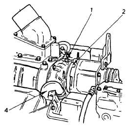
(15) Connect breather pipe (4) to cylinder block.
(16) Connect the lubricating oil tube to the fitting
in the blower drive support. Tighten
lubrication fitting (1) firmly.
(17) Install the alternator drive assembly as
detailed in para. 2-19.2.
3-108
TM 5-4210-220-34
|