|
| |
TM 5-4210-220-34
3-8.
ENGINE - Continued
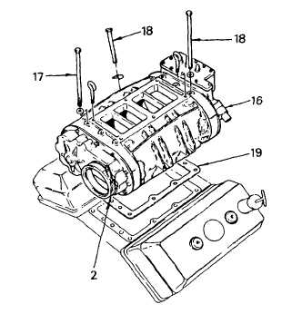
INSTALLATION
NOTE
If a new blower assembly is being installed, assemble the end plate cover (see REPAIR following),
governor, see para. 2-19.13 and fuel pump (TM 5-4210-220-12) prior to installation.
(1)
Remove all covers installed to prevent contamination from entering the cylinder block. Affix a new
blower housing gasket (19) to the cylinder block with petroleum jelly (item 21, Appendix B) to prevent
the gasket from shifting when the blower is lowered into position.
(2)
Install and clamp fuel rod cover tube hoses loosely to each side of the governor housing (16).
(3)
Install the cover seal ring and clamp (2) to the end of the blower drive support on the engine.
(4)
Thread eye bolts in diagonally opposite tapped holes in the top of the blower housing.
WARNING
Serious injury could occur if heavy equipment is
moved/lifted without sufficient personnel to do the
job . Use proper physical lifting procedures or use
a suitable lifting device or dolly. Wear safety
shoes, gloves, and other suitable protective
clothing.
(5)
Attach a chain hoist to the eye bolts. Lift
the blower assembly at a slight angle,
and lower it into position on top of the
cylinder block. Make sure the flange of
the rear end plate cover mates with the
seal ring. Completely lower the blower
assembly onto the cylinder block.
(6)
Install the 7/16 in. 14 x 8-1/4 in. blower
end plate capscrews (17) and special
washers. Install the 3/8 in. 16 x 5-1/2 in.
capscrews (18) and retaining washers
on each side of the blower housing. Do
not tighten.
NOTE
The lip on the bevelled end of the retaining washer
goes in the small recess in the blower housing just
above the bolt slot.
(7)
Slip the snap ring over the notched end of the alinement tool J33001 and thread the blower drive shaft
onto the end of the tool. Install the shaft into the rear of blower and position the blower so that the shaft
can be removed and reinstalled without drag.
3-107
|