|
| |
TM 5-4210-220-34
3-8.
ENGINE - Continued
3-8.2
Turbocharger - Continued
(29) Install piston rings (17) on thrust spacer (16). Gently Insert spacer into backplate assembly. Do not
force piston rings into place .
(30) Fasten thrust washer (19) flat against center housing with the hole and cutout in thrust washer In
alinement with pins (5) in center housing.
(31) Install thrust collar (18) against thrust washer. Lubricate with clean engine oil (item 17, Appendix B).
(32) Install new seal ring (15) in groove at compressor end of the center housing.
(33) Aline oil feed hole in center housing and backplate assembly. Attach bsckplate to center housing with
four locking tabs (13) and bolts (12). Tighten to 8 ft lb (11 Nm). Bend up corners of locking tabs to
secure bolt heads.
(34) Install new turbine piston rings (11) on wheel shaft assembly. Lubricate seal ring with clean engine oil
(item 17, Appendix B).
(35) Position wheel shroud (10) against center housing (3) Insert wheel shaft assembly through wheel shroud
and into center housing. Be careful not to scuff or scratch bearings when installing shaft assembly.
(36) Place turbine wheel shaft assembly, shroud, center housing, and backplate as assembled upright in
holding fixture or suitable socket clamped in vise. Place the extended hub of shaft into socket.
(37) Position compressor wheel over shaft.
(38) Lightly lubricate shaft threads and mounting area of wheel with clean engine oil (item 17, Appendix B).
Install compressor wheel and retaining nut. Tighten to 145 in. lb (16 Nm).
(39) Loosen nut and inspect nut face and front face of compressor wheel. Be sure they are clean and
smooth.
(40) Retighten nut to 50 in. lb (5 Nm). Continue to tighten nut for an additional 1/4 turn.
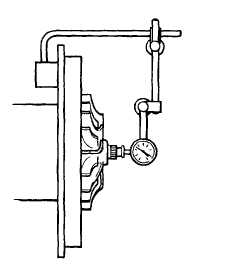
(41) Clamp center housing assembly in vise with
soft jaws. Fasten dial indicator J8001-3 and
base J7872-2 to center housing. Position so
indicator tip rests on end of rotating shaft on
compressor side. Move shaft axially back and
forth by hand. Total thrust float should be
0.003 0.010 in. (0.08 0.25 mm). If dial
indicator reading is not within specification,
replace center housing as an assembly or
replace parts to correct problem.
To prevent damage to turbine components do not pull
misalined turbine housing into alinement with the ’V’
band coupling.
3-100
|