|
| |
TM 5-4210-220-34
3-7.
TRANSMISSION - Continued
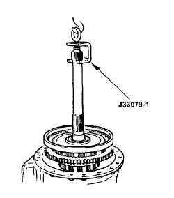
(3)
Hold air pressure in the clutch and remove
the fixture. Install lifting fixture J33079-1 to
the turbine shaft and lift into installation
position. Continue holding air pressure, and
install the forward clutch assembly.
(4)
Release the air pressure when the forward
clutch is fully seated (forward clutch will fall
slightly when air is released if the clutch is not
fully seated).
(5)
Install thrust race, cup side first, onto the
forward clutch hub. Install needle bearing
onto the race. Retain the bearing and race
with petroleum jelly (Item 21, Appendix B).
(6)
Install new center support bolt. Tighten the bolt to 46 ft lb (62 Nm).
ap.
Installation Torque Converter Housing
(1)
Place converter housing assembly on workbench so both front and rear are accessible.
(2)
Install thrust race to rear of converter housing. Retain with petroleum jelly (item 21, Appendix B). Ensure the
inner lube direction lip of the race is 0.233 in. (5.9 mm). If bearing was not installed on forward clutch
assembly, install it to converter housing using petroleum jelly (item 21, Appendix B).
CAUTION
Improper installation of the two butt-joint seal rings onto front support hub may cause transmission failure.
If humidity is allowed to penetrate and expand the butt-joint seal ring, the seal ring can be damaged during
installation. A damaged seal ring will leak oil from the clutch piston cavity and cause clutch slippage. Do
not open the sealed package until you are ready to install the seal ring.
(3)
Before installing the seal ring, the end clearance must be checked to ensure that the seal ring has not been
expanded.
(4)
Remove the seal ring from its sealed package. Place it in its operational position inside the bore that it will be
sealing.
(5)
Using a feeler gage, check the end clearance of the seal ring. The end clearance must not be less than
0.010 in. (0.25 mm).
(6)
If the end clearance is less than 0.10 in. (0.25 mm), bake the seal ring in an oven 200 300 deg. F (93 149
deg. C) for 24 hours or get a new seal ring. Recheck end clearance.
(7)
Pack the seal ring and its groove with a liberal amount of petroleum jelly (item 21, Appendix B).
3-78
|